FC9000-UM-251-9370 8-55
8 Electrical Adjustment
8.19 Adjusting the Spacing Between Tool 1 and Tool 2
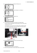
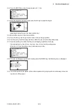
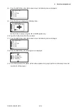
This adjustment will set the spacing between tool 1 and tool 2.
Perform this procedure if adjustment values could not copy from the SUB-NVRAM when replacing the main
board.
When the main board or the pen block was replaced or the 2nd Pen option was installed, perform this
adjustment.
8.19.1 Inputting the Spacing Between Tool 1 and Tool 2 from the
recorded value
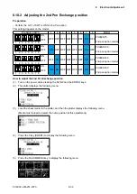
How to input the Spacing Between Tool 1 and Tool
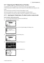
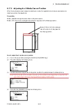
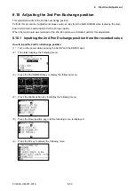
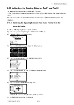
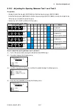
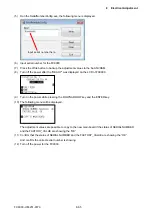
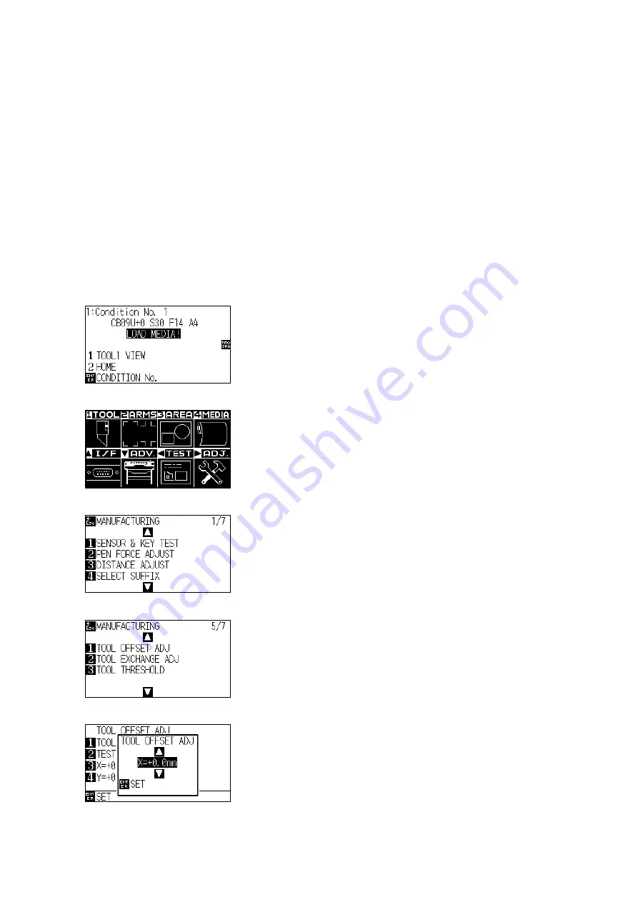
(1) Turn on the power while pressing the SLOW and the ENTER keys.
(2) The plotter displays the following menu.
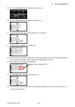
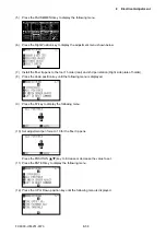
(3) Press the PAUSE/MENU key to display the following menu.
(4) Press the Right position key to display the following menu.
(5) Press the Down position key until the following menu is displayed.
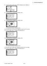
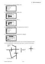
(6) Press the F3 key to display the following menu.
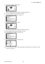
Set the X-offset value by using the UP or DOWN position key.
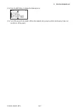
(7) Input the X-offset value from the recorded.
Summary of Contents for FC9000-100
Page 1: ...CUTTING PLOTTER SERVICE MANUAL FC9000 75 100 140 160 FC9000 UM 251 01 9370...
Page 2: ......
Page 4: ...FC9000 UM 251 9370 II...
Page 38: ......
Page 201: ...FC9000 UM 251 9370 10 2 10 PARTS LIST Outer Casing 1 2 3 4 10 7 11 5 16 15 6 12 12 9 13 14 8...

