FC9000-UM-251-9370 7-49
7 DISASSEMBLY AND REASSEMBLY
7.4
Confirming the cable wiring
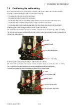
When the cables were reconnecting to the connector, confirm each cables are connected correctly.
Specially confirm the following cables are reconnected correctly.
• The cables from the X-motor to the main board.
• The cables from the Y-motor to the main board.
•
The flexible cable (Cam sensor flexible cable) from the cam sensor board to the main board.
•
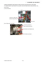
The flexible cable (Y flexible cable) from the Y relay board to the main board.
•
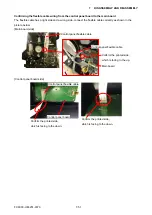
The flexible cable (Control panel flexible cable) from the control panel board to the main board.
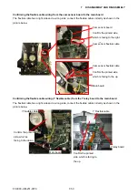
Confirming the cables wiring from the X-motor to the main board
The cables for X and Y motor has same connectors, therefore do not connect those cables incorrectly.
The X motor has the power cable and the encoder cable, connect these cables to correct connectors as
shown in the picture below.
X motor encoder cable
X motor
X motor power cable
Main board
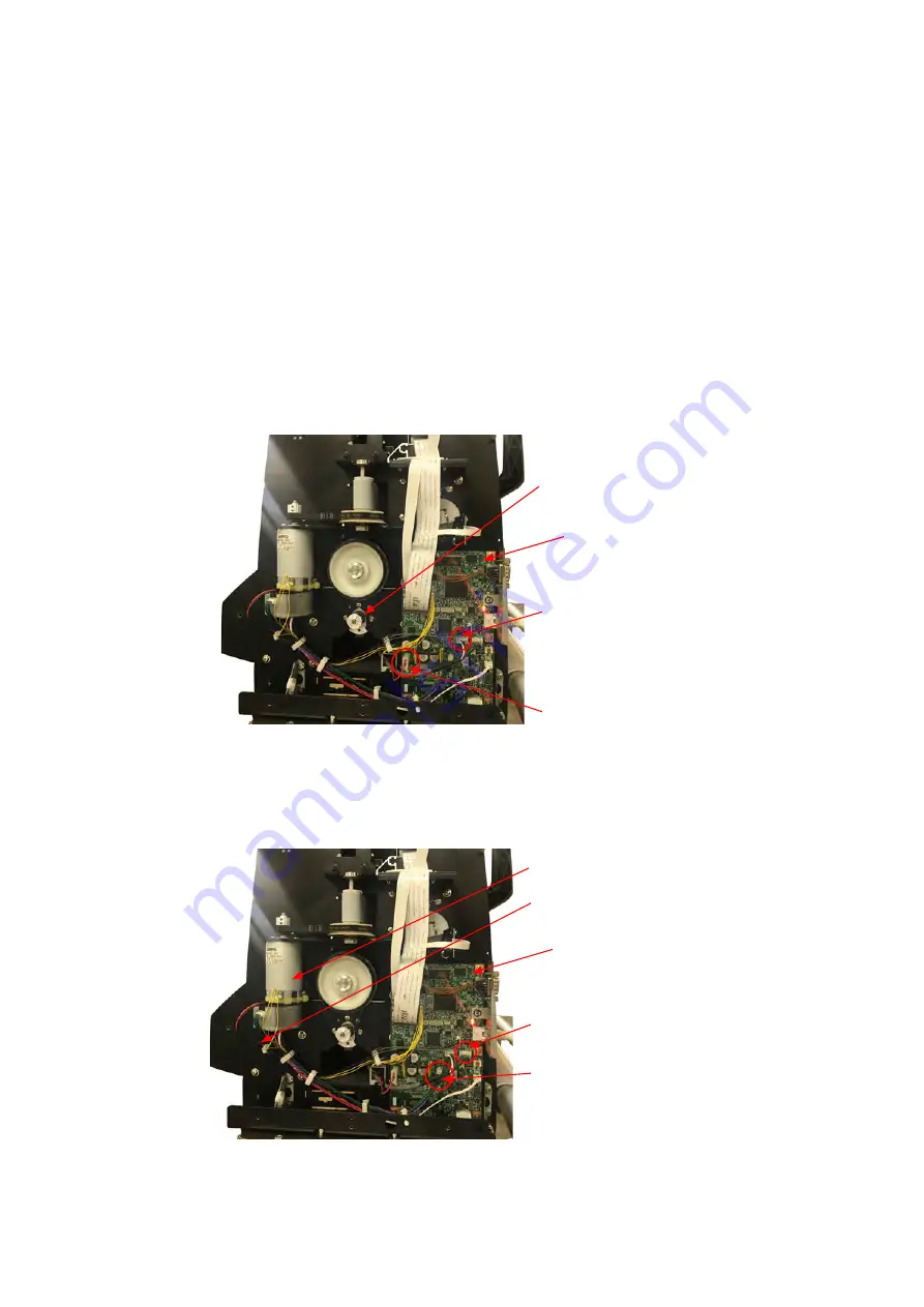
Confirming the cables wiring from the Y-motor to the main board
The cables for X and Y motor has same connectors, therefore do not connect those cables incorrectly.
The Y motor has the power cable and the power-relay cable and the encoder cable.
Connect these cables to correct connectors as shown in the picture below.
Y motor encoder cable
Y motor
Y motor power cable
Y motor power relay cable
Main board
Summary of Contents for FC9000-100
Page 1: ...CUTTING PLOTTER SERVICE MANUAL FC9000 75 100 140 160 FC9000 UM 251 01 9370...
Page 2: ......
Page 4: ...FC9000 UM 251 9370 II...
Page 38: ......
Page 201: ...FC9000 UM 251 9370 10 2 10 PARTS LIST Outer Casing 1 2 3 4 10 7 11 5 16 15 6 12 12 9 13 14 8...

