7
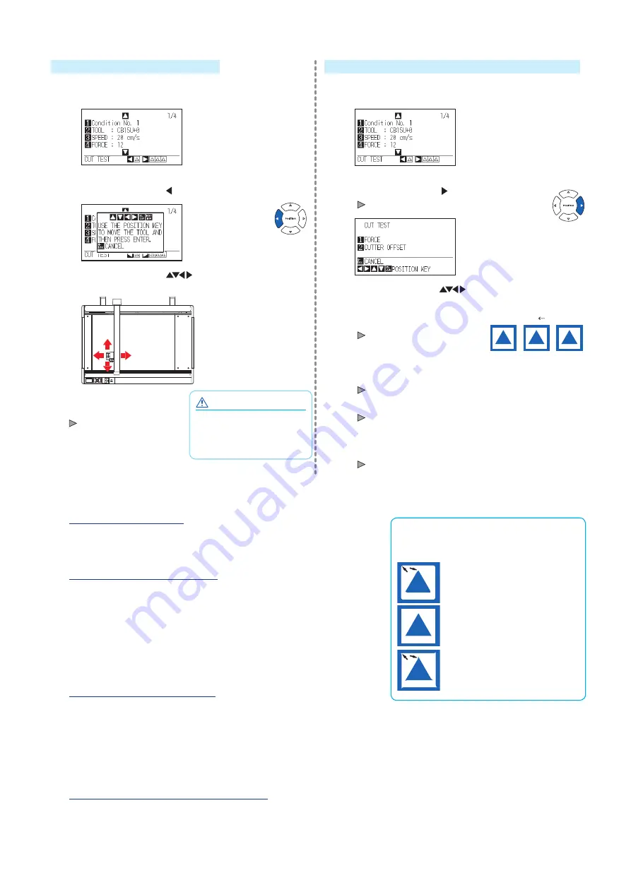
To make 1 cut with set value
4
Make test cutting for one piece while Tool conditions are
being set.
(1) Press the POSITION ( ) key (CUT TEST).
(2) Press the POSITION (
) keys to move the tool
carriage to the location you wish to perform the test cutting.
CAUTION
When the [ENTER] key is
pressed, the tool carriage will
start moving, so take care not
to cut your fingers.
Press the [ENTER] key.
1 cut test pattern is cut.
To make 3 cuts with set value and ±1 of set value
4
Make test cutting for three pieces while Tool conditions
are being set.
(1) Press the POSITION ( ) key (CUT TEST).
CUT TEST screen is displayed.
(2) Press the POSITION (
) keys to move the tool
carriage to the location you wish to perform the test cutting.
(3) Press the [1] key (FORCE).
Cut Order
+1
Setting
values
-1
3 cutting test patterns are cut,
with current FORCE in the
center, and 1 each of FORCE
increased and decreased for 1.
(4) Press the [ENTER] key after completion.
It will return to CUT TEST menu screen.
(5) Press the [2] key (CUTTER OFFSET).
3 cutting test patterns are cut, with current CUTTER
OFFSET in the center, and 1 each of CUTTER OFFSET
increased and decreased for 1.
(6) Press the [ENTER] key after completion.
It will return to CUT TEST menu screen.
5
Check if the cut test is appropriate.
Confirm the cutting test results, and adjust to optimal setting. Repeat cutting test and adjustment until optimal cut is achieved.
Adjustment of Offset
How to check offset
Check if the offset value is set correctly by
following.
Not enough adjustment.
Increase the offset value.
Optimal offset value.
Too much adjustment.
Decrease the offset value.
Check the corners of the triangles and rectangles. See "Setting the Tool
Condition" in the User’s Manual (PDF) and adjust the offset value if the
corner is not cut or if it is cut too much.
Adjustment for Half Cutting
Peel off the triangle area, and adjust so it cuts slightly into the backing sheet.
If the backing sheet has been cut through, either the FORCE setting is
too high or the cutter-blade tip is extended too far. If the backing sheet
shows only a few traces of the cutter blade, either the FORCE setting is
too low or the cutter blade tip is not sufficiently extended.
See “Adjusting the Blade Length” and “Setting the Force” in the User’s
Manual (PDF) and adjust the settings.
Adjustment for Cutting Out
Adjust so the media is completely cut out.
If the media is not completely cut, either the FORCE setting is too low or
the cutter blade tip is not sufficiently
extended.
See “Adjusting the Blade Length” and “Setting the Force” in the User’s
Manual (PDF) and adjust the settings.
Adjustment When Using Plotting Pen
Adjust the FORCE so there will be no faint lines. To prolong the pen life,
set the FORCE to the lowest setting without any faint lines. See "Setting
the Force" for the FORCE setting and adjust the settings.
Summary of Contents for FCX4000 SERIES
Page 8: ...622659111...
Page 10: ...2 2 3 1 USB 1 1 PHP33 CB15N HS 1 CB15U 1 1 PHP31 FIBER 1 KF700 BK 1P 1 PM CT 001 1 1...
Page 12: ...4 1 1 2...
Page 13: ...5 3 2 4 PDF 1 CHART HOLD OFF 2 3 CHART HOLD 4 CHART HOLD CHART HOLD CHART HOLD...
Page 14: ...6 3 PDF PDF 1 2 POSITION 3 ENTER 4 1 2 5 ENTER 4 1 2 COND TEST 1 4 PDF 3...
Page 16: ...622659111...


