GL820-UM-251-9370
3-5
3. DISASSEMBLY AND REASSEMBLY
3.5 Replacing the Main Control Board
Disassembly
(1) Remove the input terminal unit from the main unit (See Section 3.2).
(2) Remove the side pads from the main unit (See Section 3.3).
(3) Disassemble the top cover assembly and the bottom case assembly (See Section 3.4).
(4) Disconnect the LCD flexible cable from the main control board.
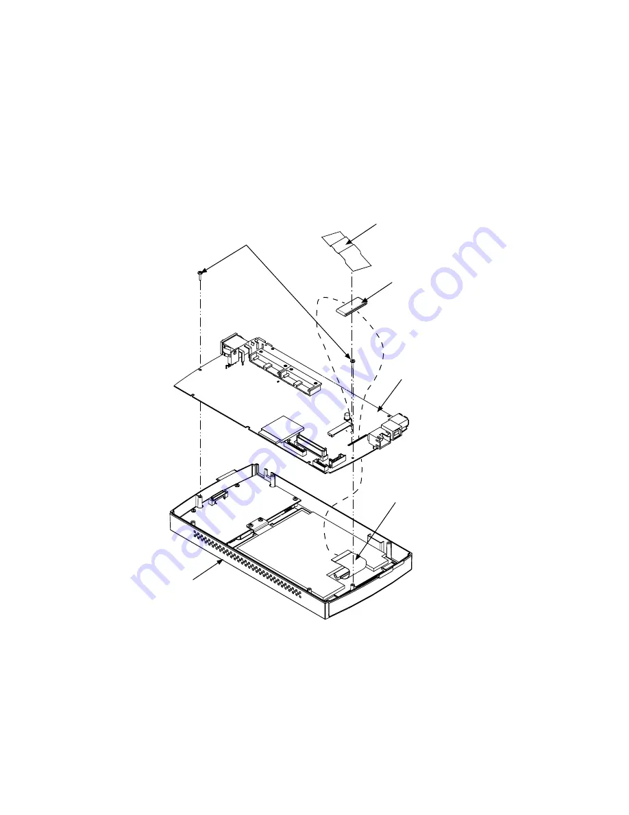
(5) Remove the two M2L6 self-tapping screws holding the main control board from the top cover assembly.
(6) Disconnect the connector between the main control board and the control panel board and then remove
the top cover assembly.
M2L6 self-tapping screw
LED flexible cable
Main control board
Top cover assembly
Core
Fixing tape
Re-assembly
(1) Re-assemble the main control board in the reverse order in which it was disassembled.
Summary of Contents for GL820
Page 1: ...midi LOGGER SERVICE MANUAL 820 GL820 UM 251 GL820 UM 251 02 9370 ...
Page 2: ......
Page 8: ...GL820 UM 251 9370 1 2 1 CONFIGURATION ...
Page 12: ......
Page 36: ......
Page 56: ......


