GL820-UM-251-9370
4-4
4. SETUP PROCEDURES
4.3 Performing Setup1 (Voltage Input)
This procedure is required when any part of the AMP board is replaced.
Preparation
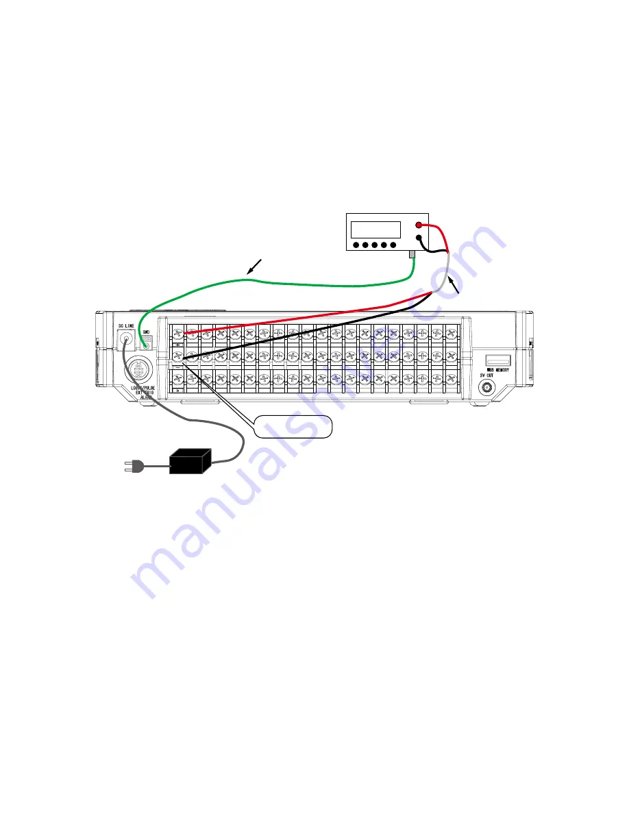
• Have a voltage generator on hand that can output voltage up to 50 VDC (four-digit output).
• Mutually connect the ground terminals of the voltage generator and the GL820.
• Set the AC Line cycle setting of the GL820 to the same cycle as that of your AC line.
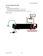
Wiring connection
0.00000 V
Voltage generator
FG
GND
AC adapter
Connect to CH1
Input cable
Connect both ends to GND
Summary of Contents for GL820
Page 1: ...midi LOGGER SERVICE MANUAL 820 GL820 UM 251 GL820 UM 251 02 9370 ...
Page 2: ......
Page 8: ...GL820 UM 251 9370 1 2 1 CONFIGURATION ...
Page 12: ......
Page 36: ......
Page 56: ......


