GL820-UM-251-9370
5-6
5. INSPECTION AND CHECK PROCEDURES
5.2 Voltage Measurement Accuracy
Supply the reference voltage or frequency determined for each measurement range, and then check the
voltage accuracy.
Preparation
• Have a voltage generator on hand that can output voltage up to 50 VDC (using four-digit output).
• Mutually connect the ground terminals of the voltage generator and the GL820 prior to initiating
measurement.
• Set the AC Line cycle setting of the GL820 to the same cycle as that of your AC line.
• Set the Sampling setting of the GL820 to at least 1 sec or longer.
Wiring connection
Same wiring connection as Setup1. (See Setup1 procedure)
Setting procedure
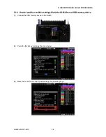
(1) Load the condition settings file "GL820ConditionVolt.CND" from the USB memory device.
Measurement procedure
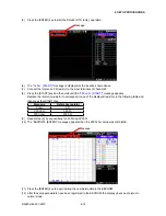
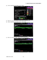
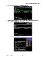
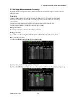
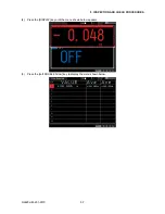
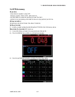
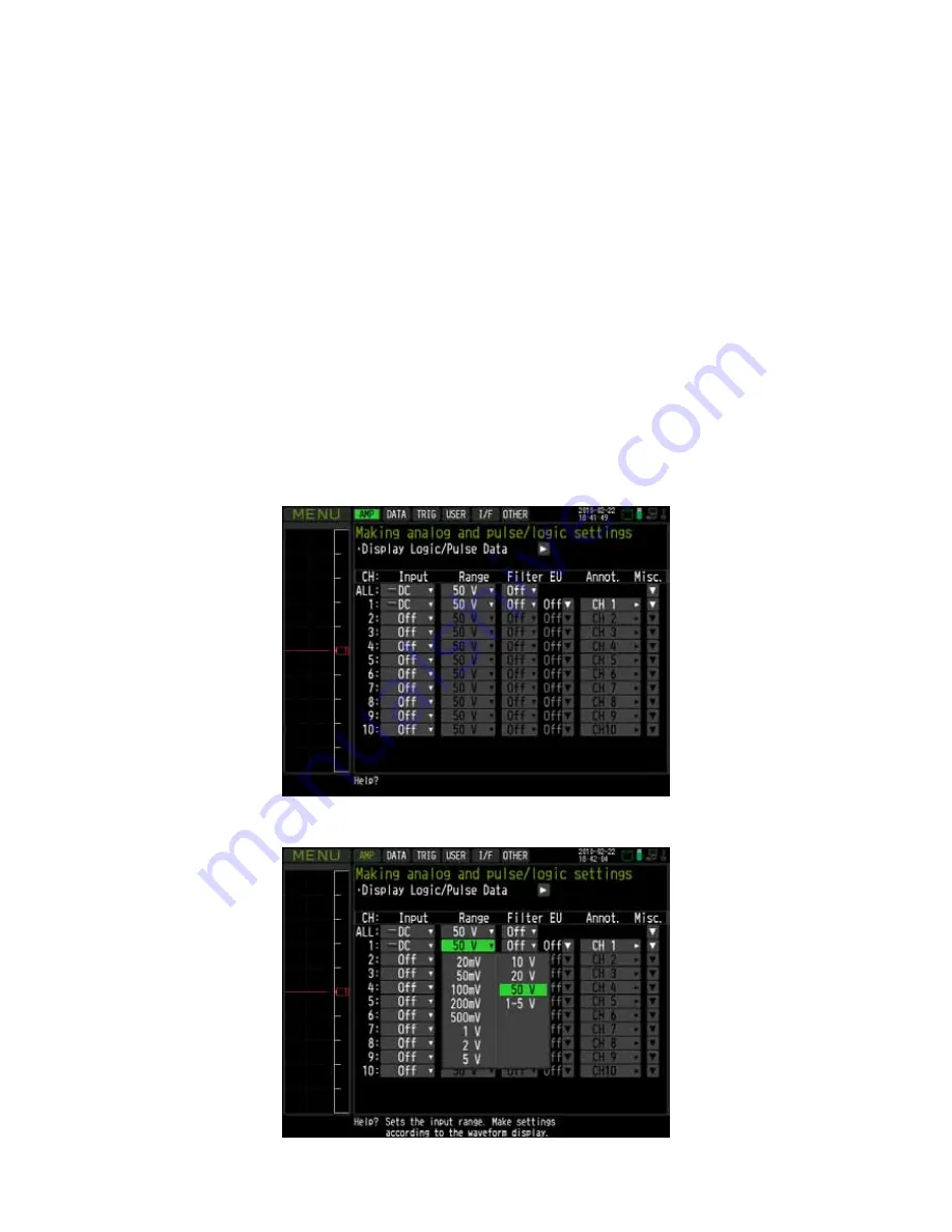
(1) Press the [MENU] key to display the menu shown below.
(2) Move the cursor to the Range position of channel 1.
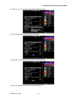
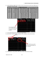
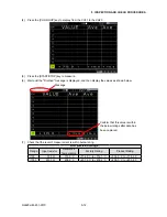
(3) Press the [ENTER] key to display the menu shown below, and then select the reference voltage range.
Summary of Contents for GL820
Page 1: ...midi LOGGER SERVICE MANUAL 820 GL820 UM 251 GL820 UM 251 02 9370 ...
Page 2: ......
Page 8: ...GL820 UM 251 9370 1 2 1 CONFIGURATION ...
Page 12: ......
Page 36: ......
Page 56: ......


