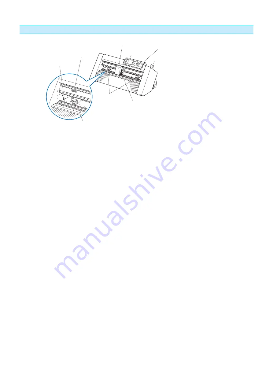
1-6
Cutter unit
(7) Cutting mat
(6) Grit roller position guide
(5) Tool carriage
(4) Tool holder
(3) Set lever
(1) Push roller
(2) Media sensors
(8) Grit rollers
(9) Control panel
(Cutter unit)
(1) Push roller ...........................This is used to press the media against the grit roller.
(2) Media sensors .....................The front sensor is used to sense the leading edge of the media. The rear
sensor is used to sense the trailing edge of the media.
(3) Set lever ..............................When loading the media to the cutting part, raise and lower the push roller to
UHOHDVHDQGÀ[WKHPHGLD
(4) Tool holder ..........................Holds the cutter-pen or plotting pen and moves it up or down.
(5) Tool carriage .......................Moves the cutter-pen or plotting pen across the media during cutting.
(6) Grit roller position guide ......Stickers on the front of the Y rail and the rear side of the top cover that show
the position of each grit roller. To move the push roller, set it within the area of
this guide in accordance with the width of media.
* Leftmost position of the roller is not used.
(7) Cutting mat .........................Cutter blade moved on this mat, preventing wears of the blade.
(8) Grit rollers ...........................This is used to feed the media back and forth.
(9) Control panel (Cutter unit) ...This is not used in this Cutter.


