SK200-UM-251-9370
3-4
3. PREPARING TO OPERATE THE SCANNER
3.4 Connecting the Scanner to a Computer
USB Connection
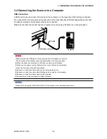
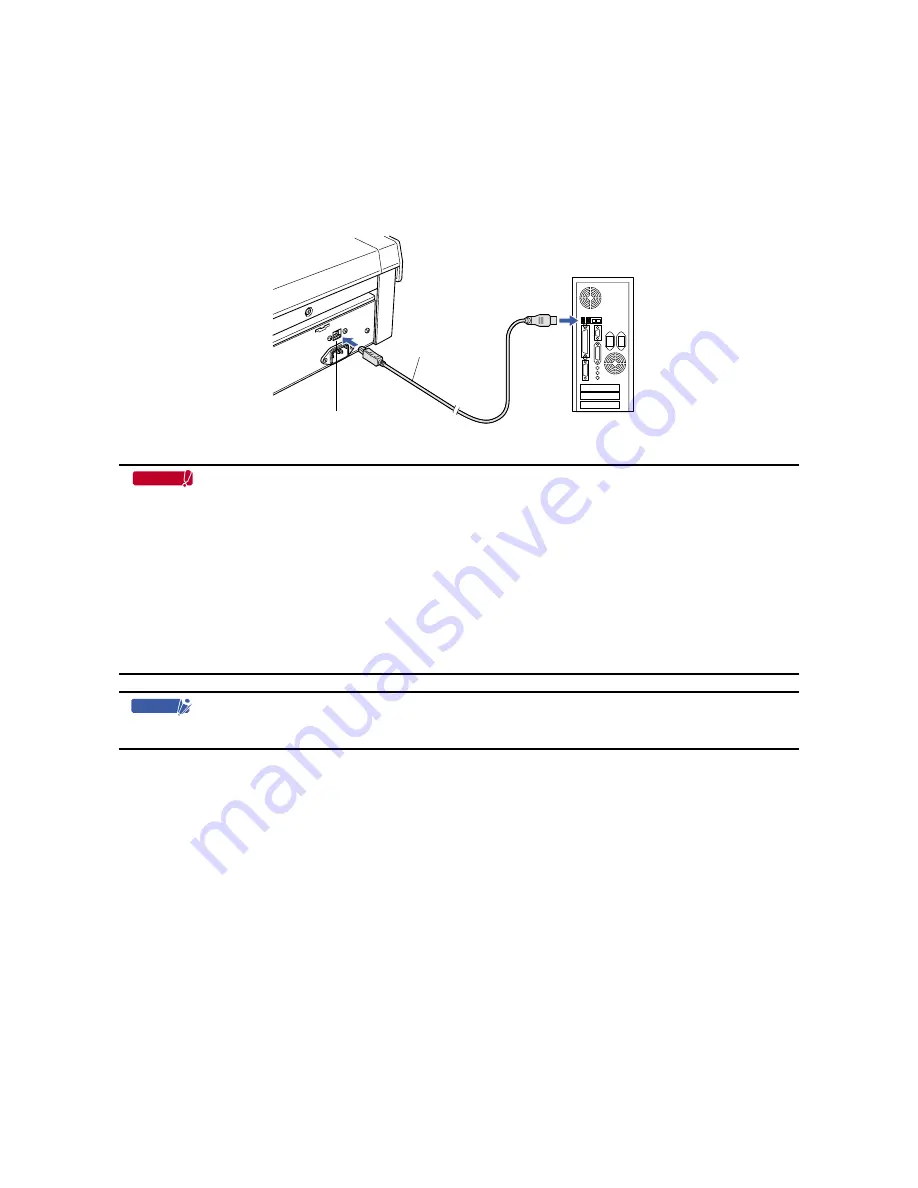
A USB cable is used to connect the scanner to the computer, via the respective USB interface connectors.
The connectors at the computer and scanner ends of the USB cable have different shapes. Make sure that
the cable is oriented correctly before making the connection.
Make sure that both the scanner and the computer are in the power-off status when connecting them.
Computer
USB interface connector
USB cable
Important
• Make sure that the USB cable is firmly inserted into the interface connectors.
• The operation of the scanner cannot be guaranteed in the following cases:
t
When the cable is connected to a USB hub or an add-on USB board.
t
When you are using a custom-built computer or one that you have modified.
• Do not perform any of the following actions:
t
Remove or reinsert the cable while you are installing the driver.
t
Remove or reinsert the cable while starting up the computer or the scanner.
t
Remove or reinsert the cable while transferring data.
t
Connect two or more scanners to a single computer.
Checkpoint
Please see the separate “Quick Start Guide” for the scanner driver installation procedure.
Summary of Contents for SK200-09
Page 1: ...SK200 UM251 03 9370 SERVICE MANUAL MANUAL NO SK200 UM 251 ...
Page 6: ......
Page 10: ...SK200 UM 251 9370 1 4 1 OVERVIEW When the scanner is mounted on the high stand 1185 720 1100 ...
Page 38: ......
Page 40: ......
Page 42: ......
Page 100: ......
Page 112: ......
Page 135: ...SK200 UM 251 9370 13 23 13 BLOCK DIAGRAM AND CIRCUIT DIAGRAMS Power Board CN4091 07 2 4 ...
Page 136: ...SK200 UM 251 9370 13 24 13 BLOCK DIAGRAM AND CIRCUIT DIAGRAMS Power Board CN4091 07 3 4 ...
Page 137: ...SK200 UM 251 9370 13 25 13 BLOCK DIAGRAM AND CIRCUIT DIAGRAMS Power Board CN4091 07 4 4 ...
Page 162: ...SK200 UM 251 9370 13 50 13 BLOCK DIAGRAM AND CIRCUIT DIAGRAMS Power Board CN4091 17A 2 4 ...
Page 163: ...SK200 UM 251 9370 13 51 13 BLOCK DIAGRAM AND CIRCUIT DIAGRAMS Power Board CN4091 17A 3 4 ...
Page 164: ...SK200 UM 251 9370 13 52 13 BLOCK DIAGRAM AND CIRCUIT DIAGRAMS Power Board CN4091 17A 4 4 ...


