6
8911 Instruction Manual
8911 AES/EBU Reclocking Distribution Ampli
fi
er
Outputs
There are eight identical outputs for the 8911 module—J1 through J8. The
destination equipment should have an input impedance of 75
Ω
unless it
has loopthrough inputs, in which case the unused loopthrough connector
must be terminated into 75
Ω
.
Testpoints and Indicators
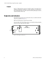
The 8911 DA has ground and +5V testpoints easily accessible on the front
edge of the module (see
Between the testpoints is a green Power On LED.
The Lock LED on the front of the module is on when the reclocking chip has
locked on the incoming AES/EBU signal.
Figure 5. 8911 Testpoints and Indicators
8911
AES/EBU
RECLOCKING DA
0544_02
Ground
Power
OK LED
Lock
LED
+5V

