
8935CF — Instruction Manual
27
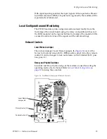
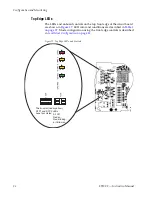
Configuration and Monitoring
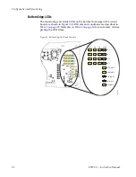
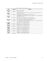
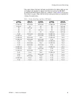
Table 1. Top Edge LED Names and Conditions
LED
Indication
Condition
FAULT
(red)
Off
Normal operation, module OK.
On continuously
Module has detected an internal fault.
Flashing
Configuration problems. Check inputs and settings. Missing video.
COMM
(yellow)
Off
No activity on frame communication bus.
Flashing
Locate Module command received by the module from a remote control system.
Pulse
(short duration
Activity present on the frame communication bus.
CONFIG
(yellow)
Off
Module is in normal operating mode, no configuration change in progress or initialization complete.
On continuously
Module is initiating or changing operating modes.
Flashing
Locate Module command received by the module from a remote control system.
PWR
(green)
Off
No power to module or module’s DC/DC converter failed.
On continuously
Normal operation, module is powered.
REM OVR
(yellow)
Off
Not used in this application.
On continuously
SFP1
(bi-color
red/yellow)
Off
No SFP submodule is not installed in position 1 (top of module).
Yellow on
A supported SFP submodule is installed in position 1 (top of module). Normal operation.
Red flashing
An unsupported SFP submodule is installed in position 1 (top of module).
Red on
continuously
The SFP submodule in position 1 (top of module) has an internal fault.
SFP2
(bi-color
red/yellow)
Off
No SFP submodule is not installed in position 2 (bottom of module).
Yellow on
A supported SFP submodule is installed in position 2 (bottom of module). Normal operation.
Red flashing
An unsupported SFP submodule is installed in position 2 (bottom of module).
Red on
continuously
The SFP submodule in position 2 (bottom of module) has an internal fault.


