8935CF — Instruction Manual
31
Configuration and Monitoring
Local Mode Configuration
Set the operating mode for each channel using the two local onboard
control components described below and shown in
Operating modes are described in
.
•
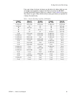
Function (rotary) switch (S2) – this switch is used to access each of the
four channels for configuration. The switch has 16 possible positions (0
through 9 and A through F). Only positions 1, 2, 3, 4, and F are used (see
Note
The Function switch should be parked in an unused position such as 0 during
normal operation to avoid changing the mode accidently with the paddle
switch.
•
Paddle switch (S1) – scrolls through the available modes for the selected
channel when the switch is held momentarily in either the up or down
position.
•
CONFIG (configuring) LED – when on, indicates the module is initial-
izing or processing configuration information.
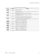
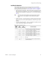
Table 4. Mode Configuration Functions
Function
Switch
Setting
Paddle
Switch Up
Paddle
Switch Down
Function Description
0
–
–
Park position for normal operation (paddle switch has no effect)
1
Increment
Decrement
Set Channel 1 operating mode as Auto/Mute, Fixed 270M/Mute,
Fixed 1.5G/Mute, Auto/Bypass, or Fixed Bypass.
2
Increment
Decrement
Set Channel 2 operating mode as Auto/Mute, Fixed 270M/Mute,
Fixed 1.5G/Mute, Auto/Bypass, or Fixed Bypass.
3
Increment
Decrement
Set Channel 3 operating mode as Auto/Mute, Fixed 270M/Mute,
Fixed 1.5G/Mute, Auto/Bypass, or Fixed Bypass.
4
Increment
Decrement
Set Channel 4 operating mode as Auto/Mute, Fixed 270M/Mute,
Fixed 1.5G/Mute, Auto/Bypass, or Fixed Bypass.
5-9
–
–
Not used
A-E
–
–
F
Recall
Recall factory defaults (all channels have Reporting Enabled and
Auto/Mute mode selected).

