background image

18

8935CF — Instruction Manual

Installation


Cabling

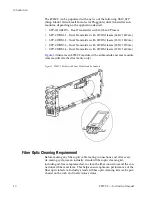
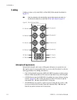
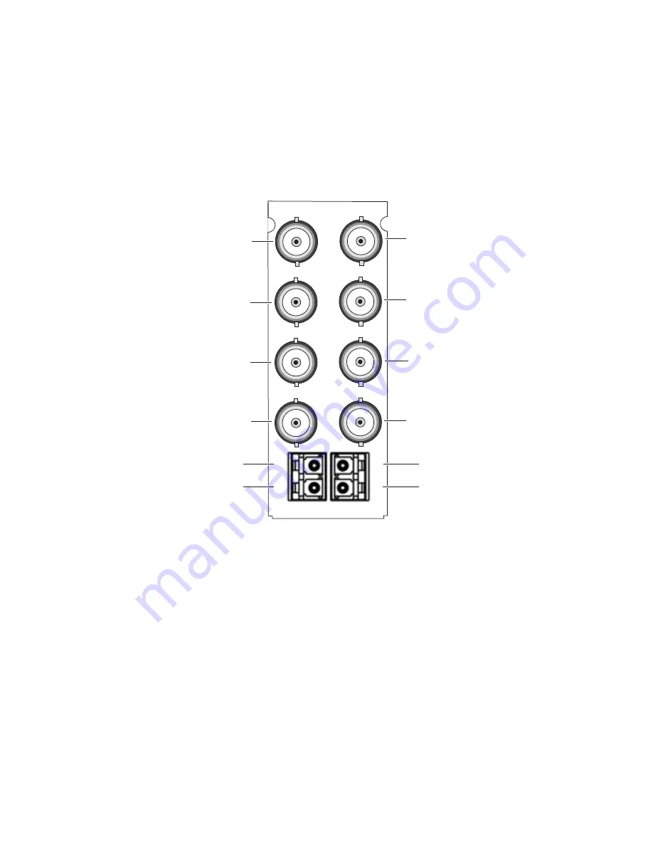
Cabling is done on the rear BNCs of the 8935CF-R module illustrated in 

Figure 10

.

Note

Read the precautions for handling fiber optics before making connections to 
the fiber optic connectors as described in 

Fiber Optic Outputs

 on page 19

.

Figure 10.  8935CF-R Rear Module

Attenuation Requirements

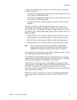
Some shorter length cable runs will require attenuation to prevent over-
driving the receiver causing bit errors to occur on the fiber link. Use the fol-
lowing guidelines for adding attenuation:

The 1310nm Dual Transmitter (SFP-1310-SDTX) requires no attenuation 
between fiber transmitter and receiver connections at any cable lengths.

CWDM devices used with 8939FCA modules for a mux/demux config-
uration (

page 20

) with a cable run from 0-12 km (7.5 miles), must be 

attenuated by 3 dB between 8939CFA COM ports.

All CWDM devices used in a point-to-point configuration with a cable 
run from 0-20 km (12.4 miles), must be attenuated by 5 dB between 
fiber transmitter and receiver connections.

8543_03

8935CF-R

OUT

OUT

IN

OUT

CH1

IN

1

2

3

4

OUT

CH2

IN

OUT

CH3

IN

OUT

CH4

CH 1 Electrical In

CH 1 Electrical Out

CH 1 Fiber Out

CH 2 Fiber Out

CH 2 Electrical In

CH 2 Electrical Out

CH 3 Electrical Out

CH 3 Electrical In

CH 3 Fiber Out

CH 4 Fiber Out

CH 4 Electrical In

CH 4 Electrical Out

Summary of Contents for 8935CF -

Page 1: ...8935CF 4 CH ELECTRICAL TO FIBER CONVERTER Instruction Manual SOFTWARE VERSION 1 0 0 071854300 MAY 2007 ...

Page 2: ... Blvd Salt Lake City UT 84119 United States 7140 Baymeadows Way Suite 101 Jacksonville FL 32256 United States Including its implementation meets the requirements of the standard ISO 9001 2000 Scope The design manufacture and support of video hardware and software products and related systems This Certificate is valid until June 14 2009 This Certificate is valid as of August 30 2006 Certified for t...

Page 3: ...8935CF 4 CH ELECTRICAL TO FIBER CONVERTER Instruction Manual SOFTWARE VERSION 1 0 0 071854300 MAY 2007 ...

Page 4: ... 20 800 8080 2020 or 33 1 48 25 20 20 United States Canada 24 x 7 1 800 547 8949 or 1 530 478 4148 Local Support Centers available during normal business hours Asia Hong Kong Taiwan Korea Macau 852 2531 3058 Indian Subcontinent 91 22 24933476 Southeast Asia Malaysia 603 7805 3884 Southeast Asia Singapore 65 6379 1313 China 861 0660 159 450 Japan 81 3 5484 6868 Australia and New Zealand 61 1300 721...

Page 5: ...iber Optic Outputs 19 Configuration and Monitoring 23 Operating Modes Overview 23 Auto Mute Mode Default 23 Fixed 270M Mute Mode 24 Fixed 1 5G Mute Mode 24 Auto Bypass Mode 24 Fixed Bypass Mode 24 Local Configuration and Monitoring 25 Onboard Controls 25 Top Edge LEDs 26 Bottom Edge LEDs 28 Local Mode Configuration 31 Remote Monitoring and Controls 32 8900NET Module Information 32 Web Browser Inte...

Page 6: ...6 8935CF Instruction Manual Contents Power Up Diagnostic Failure 53 Troubleshooting 53 Electronic Circuit Breaker 53 Voltage Test Points 53 Module Repair 54 Functional Description 54 Index 55 ...

Page 7: ...dules in the GeckoFlex frame As part of this family of modular products it is subject to the Safety and Regulatory Compliance information described in the GeckoFlex Frames Instruction Manual When using any of the fiber optic options refer to the laser compliance information in the GeckoFlex Frames Instruction Manual for safety informa tion ...

Page 8: ...8 8935CF Instruction Manual Preface ...

Page 9: ...le mode SFP dual transmitter fiber optic submodules mounted on the front module Up to ten 8935CF modules in the same 2 RU GeckoFlex frame Four electrical BNC inputs to up to four fiber optic outputs and an iden tical electrical BNC output for each channel Re clocking for stable long distance signals or re clocking bypass for non SDI signals Supports both HD or SD formats and passes embedded audio ...

Page 10: ...DM 4 Dual Transmitter with CWDM lasers 1590 1610nm Figure 1 illustrates an 8935CF module with a submodule and rear module rear module attached for clarity only Figure 1 8935CF Module with Rear Module and Submodule Fiber Optic Cleaning Requirement Before making any fiber optic cable mating connections and after every de mating cycle use an industry standard fiber optic cleaning kit including oil fr...

Page 11: ...t 2 Installing the SFP fiber submodules on the front module 3 Placing the front module in the corresponding front slot 4 Cabling the signal ports and 5 Setting module parameters with on board switches or with the web browser interface All GeckoFlex front and rear modules can be inserted and removed from an GeckoFlex frame with power on Note Modules and submodules are sensitive to static damage use...

Page 12: ... and pull it off Note To remove a rear module already installed follow the same steps It is helpful to first remove the front module so the rear can be pulled out more easily 3 Before installing the 8935CF rear module check that the blue plastic fiber optic connectors on the rear module are not mounted too rigidly They should not be locked tightly in place You should be able to move the connectors...

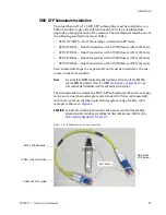
Page 13: ... be installed by the cus tomer on the front module Note For using the CWDM full functionality mux demux format with the 8939CA and the 8935FC modules refer to CWDM Configuration on page 20 for spe cific submodule installation location and cabling information The submodule kit includes one SMV_SFP submodule with dust cover pro tector and a dual channel single mode standard LC fiber cable assembly w...

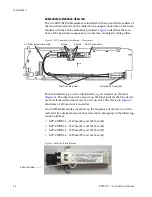
Page 14: ...t number on the label Figure 6 The direction of the arrows on the label indicate that the device is a dual transmitter dual receiver or transceiver The device in Figure 6 illustrates a 1310nm dual transmitter On CWDM submodules not shown the frequency of the device will be indicated by numbers between the arrows that correspond to the following model numbers SFP CWDM 1 1440nm 44 and 1490nm 49 SFP ...

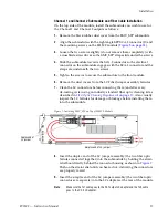
Page 15: ... dust covers from the LC Fiber Jumper assembly ferrules 7 Clean the LC connectors before connecting them and after every de mating cycle using an industry standard fiber optic cleaning kit as described in Fiber Optic Cleaning Requirement on page 10 Also visually inspect the LC ferrules for damage or blockage before installing them into the submodule Figure 7 Installing SMV_SFP on Top of 8935CF Mod...

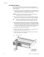
Page 16: ...el 4 Submodule and Fiber Cable Installation Repeat this procedure for the second submodule on the other side bottom of the module Figure 8 illustrates the bottom of the module This sub module will output Channel 3 and Channel 4 and will install in SCA 2 con nector J2 Note Make sure the Tx3 cable goes to the Ch 3 output LC adapter and the Tx4 cable goes to the Ch 4 LC adapter Figure 8 Installing SM...

Page 17: ...Optic Cleaning Requirement on page 10 5 Insert the front module so that the plastic card guides on the module top and bottom edges go over the upper and lower raised rail guides on the right of the top and bottom of the slot Figure 9 6 Carefully slide the module into the rear connector 7 Lock the front module ejector tab into the locking pin 8 Replace the front cover for configuring the module usi...

Page 18: ...smitter SFP 1310 SDTX requires no attenuation between fiber transmitter and receiver connections at any cable lengths CWDM devices used with 8939FCA modules for a mux demux config uration page 20 with a cable run from 0 12 km 7 5 miles must be attenuated by 3 dB between 8939CFA COM ports All CWDM devices used in a point to point configuration with a cable run from 0 20 km 12 4 miles must be attenu...

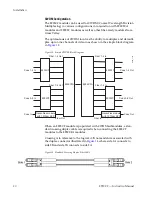
Page 19: ...ng Requirement on page 10 For the fiber output ports the 8935CF R rear module shall follow the channel allocation convention shown in Figure 11 Optical channel 1 and channel 3 are mapped to the B side of standard duplex fiber connector and channel 2 and channel 4 are mapped to the A side of a standard duplex fiber connector Figure 11 8935CF to 8935CF Fiber Transmit Channels 8935CF to 8935FC Connec...

Page 20: ...k Diagram When an 8935CF module is populated with CWDM submodules a stan dard crossing duplex cable is required when connecting the 8935CF modules to the 8939CFA modules Crossing is in reference to the logical A B nomenclature associated with the duplex connector illustrated in Figure 14 where side 1A connects to side 2B and side 1B connects to side 2A Figure 14 Standard Crossing Duplex Fiber Cabl...

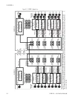
Page 21: ...1570nm frequencies SFP CWDM 4 Dual Transmitter 1590nm and 1610nm frequencies Note The four submodules can be installed in any location on the two 8935CF modules as long as the outputs are cabled to the correct frequency input on the 8935CFA The installation configuration shown here is for clarity only The 1310nm fiber output from a Grass Valley GeckoFlex module is cabled to the EXP Expansion port ...

Page 22: ...SFP DRX 1 1270 1610nm SFP DRX 1 1270 1610nm COM EXP CH1 1470nm CH2 1490nm CH4 1530nm CH3 1510nm CH4 1570nm CH5 1550nm CH8 1610nm CH7 1590nm 8939FCA COM EXP CH1 1470nm CH2 1490nm CH4 1530nm CH3 1510nm CH4 1570nm CH5 1550nm CH8 1610nm CH7 1590nm 8935FC Electrical Outputs Location A Location B 8935FC Fiber Inputs 1 2 4 3 IN IN 8935CF Fiber Outputs 1 2 4 3 OUT OUT GeckoFlex Fiber Ready Module 1310 DTL...

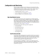
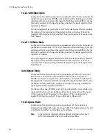
Page 23: ...bed in this section Input signal monitoring differs between modes as described in each mode section below For an input signal moni toring summary refer to Table 3 on page 30 The 8935CF supports the following modes of operation Auto Mute mode Fixed 270M Mute mode Fixed 1 5G Mute mode Auto Bypass mode Fixed Bypass mode Auto Mute Mode Default In this mode the electrical inputs are equalized and fed t...

Page 24: ...detected by the module the output of the reclocker will be muted and the outputs will be static muted With input reporting enabled the signal input will be reported as Not Present Auto Bypass Mode In this mode the electrical inputs are equalized and fed to the reclocker The bit rate is analyzed by the module If the bit rate is analyzed as 270Mb s 1 5Gb s or any bit rate above 19Mb s the module wil...

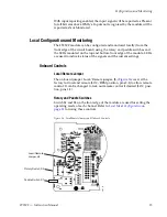
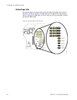
Page 25: ...the module LEDs are used to indicate status of the signals and the current settings Onboard Controls Local Remote Jumper The on board jumper Local Remote jumper J8 Figure 16 is set at the factory for local and remote LOC REM position pins 2 3 to allow remote control It can be changed to lock out remote control if desired LOC posi tion pins 1 2 Rotary and Paddle Switches Switch S1 and S2 on the fro...

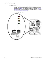
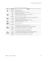
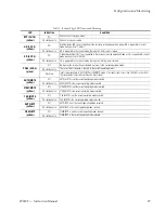
Page 26: ...igure 17 LED color and conditions are described in Table 1 on page 27 Mode configuration using the front edge controls is described in Local Mode Configuration on page 31 Figure 17 Top Edge LEDs and Controls 8543_06 FAULT COMM REM OVR SFP1 SFP2 CONFIG POWER The bi color red or yellow SFP1 and SFP2 LEDs have four states All Off Red on Red blinking or Yellow on ...

Page 27: ...from a remote control system PWR green Off No power to module or module s DC DC converter failed On continuously Normal operation module is powered REM OVR yellow Off Not used in this application On continuously SFP1 bi color red yellow Off No SFP submodule is not installed in position 1 top of module Yellow on A supported SFP submodule is installed in position 1 top of module Normal operation Red...

Page 28: ...front edge of the circuit board are shown in Figure 18 LED color and conditions are described in Table 2 on page 29 Refer also to Table 3 on page 30 for a summary of inter preting the LED states Figure 18 Bottom Edge LEDs and Controls 8543_05 BYP HD SD PRES CH1 CH2 CH3 CH4 AUTO BYP AUTO MUTE 270M MUTE 1 5G MUTE FIXED BYP ...

Page 29: ...nt in the current operating mode On continuously The correct input standard is present in the current operating mode Flashing Input is indeterminate In AUTO BYP or FIXED BYP mode if the input signal is less than 19 Mb s such as AES the carrier detect circuit will not detect an input signal AUTO MUTE yellow Off AUTO MUTE is not the current operating mode selected On continuously AUTO MUTE is the cu...

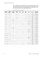
Page 30: ...eclocked 270Mb s Disabled Not Monitored Enabled Present Auto Bypass Present 1 5Gb s Green Off Yellow Off Reclocked 1 5Gb s Disabled Not Monitored Enabled Present Auto Mute Not Present N A Off Off Off Off Mute Disabled Not Monitored Enabled Not Present Auto Mute Present Not 270M or 1 5Gb s Off Off Off Off Mute Disabled Not Monitored Enabled Not Present Auto Mute Present 270Mb s Green Yellow Off Off...

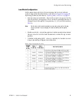
Page 31: ...h is held momentarily in either the up or down position CONFIG configuring LED when on indicates the module is initial izing or processing configuration information Table 4 Mode Configuration Functions Function Switch Setting Paddle Switch Up Paddle Switch Down Function Description 0 Park position for normal operation paddle switch has no effect 1 Increment Decrement Set Channel 1 operating mode a...

Page 32: ...le Provides complete access to all module status and configuration func tions including factory parameter default recalls slot configuration and SNMP monitoring controls Web access will require some normal network time delays for pro cessing of information Configuration parameter changes may require pressing Apply button or Enter upload processing time and a manual screen refresh to become effecti...

Page 33: ...3_01r0 The Links section lists the frame and its current modules The selected link s Status page is first displayed and the sub list of links for the selection is opened The sub list allows you to select a particular information page for the selected device Content display section displays the information page for the selected frame or module frame slot icons are also active links Refresh button f...

Page 34: ...bmodules and module slot serial number and software firmware version information page 35 Settings reports the input signal status locked rate and SFP device type and provides controls for setting the operating mode and enabling or disabling input reporting for each of the four channels page 42 Slot Config provides Locate Module and Slot Memory functions along with links to the 8900NET SNMP LED Rep...

Page 35: ...tatus of the 8935CF R module Front Processing Module indicates status of the 8935CF front module Fiber Module 1 Top indicates the status of the SFP fiber optic module installed in Position 1 on the top side of the module Fiber Module 2 Bottom indicates the status of the SFP fiber optic module installed in Position 2 on the bottom solder side of the module Color coding of the display and the Status...

Page 36: ...re 21 show all inputs present and locked and no errors of any type Examples of common errors on the Status web page are given in this section beginning with Figure 22 on page 37 Figure 21 8935CF Status Web Page No Error Messages Warning message area Optic device signal status and model number ...

Page 37: ...F Instruction Manual 37 Configuration and Monitoring Figure 22 illustrates the Status web page reporting that the top SMV_SFP submodule is not installed Figure 22 8935CF Status Web Page No Top SFP Installed ...

Page 38: ... reporting that the wrong type of SMV_SFP submodule is installed in the top position The 8935CF will accept only Dual Transmitter fiber optic submodules manufactured by Grass Valley The correct submodule types are listed under Module Features on page 9 Figure 23 8935CF Status Web Page Wrong SFP Type ...

Page 39: ...ates the Status web page reporting that the SMV_SFP sub module installed in the top position is from the wrong manufacturer The 8935CF will only accept Dual Transmitter fiber optic submodules manufac tured by Grass Valley Figure 24 8935CF Status Web Page Wrong SFP Manufacturer ...

Page 40: ...itoring Figure 25 illustrates the Status web page reporting that the SMV_SFP sub module installed in the bottom position is not recognized as the correct type or is reporting an internal error bad Figure 25 8935CF Status Web Page Unknown SFP Installed ...

Page 41: ...resent N A N A Not Present N A N A Not Present N A Not Present N A N A N A Not Present Not Present Present Not Monitored Not Monitored Not Monitored Present Not Monitored Present Not Monitored Not Monitored Present Not Monitored Not Monitored Present Not Monitored Present Not Monitored Not Monitored Not Monitored Present Present Present Present Not Monitored Not Monitored Present Present Not Monit...

Page 42: ...channel Optical Device 1 and 2 reports the signal status and type of SFP optical device installed in the top position 1 Channels 1 and 2 or the bottom position 2 Channels 3 and 4 location Set the following controls for each channel Enable Input Reporting disable input reporting to the module and upper level devices such as the 8900NET module Disabling this reporting will gray out the corresponding...

Page 43: ...ring Figure 26 Settings Web Page Signal Present The Settings web page shown in Figure 27 illustrates the reporting of an input signal other than 270Mb s or 1 5Gb s in Auto Bypass mode as being Not Monitored Figure 27 Setting Web Page Signal Not Monitored ...

Page 44: ...e Slot Config web page shown in Figure 28 to perform the following functions on the module Locate Module Slot Identification Slot Memory Frame Health Reporting LED Reports SNMP Trap Reports Each of these functions is described in detail below Figure 28 Slot Config Web Page Use this link ...

Page 45: ... not saved When the Restore upon Install box has been checked the current configuration saved to this slot is saved as slot memory When the current module is removed and another module of the same type and software version is installed the configuration saved to the 8900NET module will be down loaded to the new module The box must be checked before the current module with the saved configuration i...

Page 46: ...dule Using this web page any of these conditions can be disabled from being reported to the 8900NET module for each individual module in the frame SNMP Trap Reports Link Select the SNMP Trap Reports link to open the 8900NET SNMP Reporting web page This link will only be present when SNMP Agent software has been installed on the 8900NET module This web page allows configura tion of which alarms and...

Page 47: ...s 0 5 SMPTE 292M 1998 Tolerance bit rate 1 485 Gb s 0 5 Equalization cable length for any of the above signal types Up to 300 meters of Belden 1694A cable for bit rates up to 270 Mb s Up to 100 metes of Belden 1694A cable for bit rates 270 Mb s and 1 485 Gb s Input jitter tolerance reclock mode 1 UI p p 10 Hz to 1k Hz 0 2 UI p p 1k Hz to 15 MHz Input jitter tolerance bypass mode 1 UI p p 10 Hz to ...

Page 48: ...3 2 and GR 20 CORE requirements Maximum attenuation of 0 4 dB km 1310nm Maximum attenuation of 0 3 dB km 1550nm Standard Other than LC connector conforms to SMPTE 297M 2006 Polarity Non inverting Total jitter 0 2 UI p p Input to Output Jitter transfer 1 dB peaking in jitter transfer function form 10Hz to 10 MHz Intrinsic jitter 0 1 UI p p Electrical Length Reclocked at 270 Mb s 10 ns Reclocked at ...

Page 49: ...r Single mode fiber Data rate 143 Mb s to 1 485 Mb s 143 Mb s to 1 485 Mb s Wavelength 1 1310nm 1470nm 1510nm 1550nm 1590nm Wavelength 2 1310nm 1490nm 1530nm 1570nm 1610nm Power output 9 to 3 dBm 0 126 mW to 0 501 mW 0 to 3 dBm 1 mW to 1 mW Maximum distance with SFP DRX 1 10 km 50 km 1 1 For attenuation requirements refer to Attenuation Requirements on page 18 Minimum distance with SFP DRX 1 0 km ...

Page 50: ...atus of modules power supplies fans and other status items depending on the method of monitoring being used 8900 Frame status will report the following items Power supply health Status of fans in the frame front cover Temperature Module health Frame bus status Module health status will report the following items Internal module state and state of submodule or options enabled including configuratio...

Page 51: ...in the 8900NET Network Interface Instruction Manual Frame Alarm A Frame Alarm connection is available on pins 8 and 9 of the RS 232 con nector on the rear of GeckoFlex frame Frame Monitor or 8900NET Network Interface module required This will report any of the status items enabled with the 8900NET or Frame Monitor module configuration DIP switch Connection and use of the Frame Alarm is covered in ...

Page 52: ...idual configuration web pages SNMP Reporting The GeckoFlex 8900 Series system uses the Simple Network Monitoring Protocol SNMP internet standard for reporting status information to remote monitoring stations When SNMP Agent software is installed on the 8900NET module enabled status reports are sent to an SNMP Manager such as the Grass Valley s NetCentral application There are both hardware and sof...

Page 53: ... shoot Return the unit to Grass Valley see Module Repair on page 54 Troubleshooting Electronic Circuit Breaker An electronic circuit breaker on the module works during a fault condition or an overcurrent to cut off power to the module in place of a fuse If power has been cut off to module remove the module and replace it in the frame to reset If the problem persists contact Grass Valley Customer S...

Page 54: ...ule to a designated Grass Valley repair depot Call your Grass Valley Customer Service representative for depot locations Refer to Contacting Grass Valley on page 4 at the front of this document for the Grass Valley Customer Service contact information Functional Description An overall block diagram for the 8935CF module is shown in Figure 30 Figure 30 8935CF Block Diagram ...

Page 55: ...ng local controls 31 using remote GUI 32 CWDM Coarse Wavelength Division Multiplexing configuration 20 device list 48 features 9 specifications 49 D documentation online 4 duplex fiber cable crossing 20 non crossing 19 E enable input reporting 42 enable SNMP 52 F factory defaults recalling with local controls 31 recalling with remote controls 42 FAQ database 4 FAULT LED states 27 troubleshooting 5...

Page 56: ...pdating software 50 Newton Control Panel 32 O online documentation 4 operating mode configuring with remote controls 42 overview 23 setting with local controls 31 P Paddle switch location 25 paddle switch 31 PRES LED 29 PWR LED 27 R report enable switches 52 Rotary switch location 25 rotary switch 31 S SD LED 29 service 53 Settings web page 42 SFP1 LED 27 SFP2 LED 27 Slot Config web page 44 slot m...

Page 57: ...dge LEDs 25 remote status reporting 35 Status web page 35 T troubleshooting 53 V video inputs coax 19 video outputs coax 19 voltage test points 53 W warning messages on Status web page 35 web browser interface links 34 overview 32 web site documentation 4 FAQ database 4 Grass Valley 4 software download 4 ...

Page 58: ...58 8935CF Instruction Manual Index ...

Reviews: