18
8960ENC Instruction Manual
Configuration
Local Onboard Module Configuration
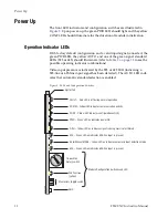
The 8960ENC module can be configured locally using the rotary and toggle
switches shown in
. Two LEDs (CONF and 2nd) indicate status of
the configuration process. These four components perform the following:
•
Function (rotary) switch addresses a desired function for configuration
and provides two sets (banks) of 16 functions (0 through 9, A through
F), although not all positions are used.
•
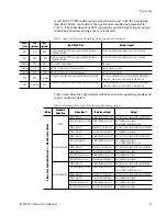
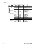
2nd (second function) LED when on, indicates that the rotary switch is
addressing the second (Bank 2) of functions (see
)
that control the optional 8900FSS Frame Sync Submodule.
•
SW1 (paddle) switch actuates or selects the desired setting for the
selected function when the switch is held momentarily in either the up
or down position.
•
CONF (configuring) LED when on, indicates the module is initializing
or processing configuration information.
Note
Function switch position F (Recall) in Bank 1 can be used to return the
module configuration to the factory default.
The following onboard jumpers are used to permit or lockout remote
control and set reference input impedance.
•
Remote Control Lockout – When a jumper is placed across pins 1 and 2
of jumper block JP1 (see
), module output mode settings are
adjustable from the Local on-board switches only. To have both Local
and Remote access, set the jumper across pins 2 and 3.
•
Reference Input Impedance – When a jumper is placed across pins 1
and 2 of jumper block JP10 (525 line reference) or JP11 (625 line refer-
ence), Reference Input is terminated into 75
Ω
). To have
high impedance termination, set the jumper across pins 2 and 3 of the
appropriate jumper block.
Figure 6. Module Configuration Switches, LEDs, and Jumpers
GRASS VALLEY GROUP 8 9 6 0 E N C C O M P O S I T E E N C O D E R 6 7 1 - 4 6 9 8 -
GND
FUNCTION – rotary switch
SW1 – actuator toggle switch
2nd – second function LED
CONF – configuration LED
JP1 Place jumper in
Local position to
lock out remote
access.
Local
Local &
Remote
JP1
JP10
JP11
Remote Lockout
Reference Input
Impedance
75
Ω
Hi Z
JP11 (625)
75
Ω
Hi Z
0642_07r1
Summary of Contents for 8960ENC -
Page 4: ...4 8960ENC Instruction Manual Contents Index 49 ...
Page 6: ...6 8960ENC Instruction Manual Preface ...
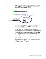
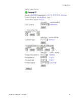
Page 33: ...8960ENC Instruction Manual 33 Configuration Figure 17 Timing Web Page ...
Page 34: ...34 8960ENC Instruction Manual Configuration Figure 18 Timing Web Page Slider Controls ...
Page 38: ...38 8960ENC Instruction Manual Configuration Figure 21 8960ENC Slot Config Web Page ...


