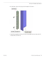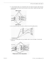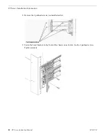
10. Reinstall the system backplane in the rear of the chassis by inserting it straight into the slot then
sliding it all the way to the left. Fasten the thumb screws securely by turning to the right.
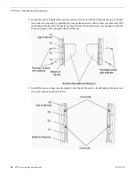
11. Reinstall the front unit containing the DVD drive and LED module in the front of the chassis in
the reverse order done in Step 1 of this procedure.
12. Now install the two CPU/IO modules as described in the next section.
Install CPU/IO modules
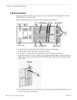
This procedure explains how to install the CPU/IO modules into the chassis enclosure once it is
installed in the rack. It is recommended to have two people available to do this procedure.
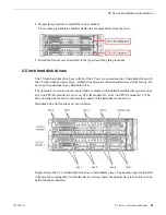
There are two CPU/IO modules in the system, Module 0 (in the top slot) and Module 1 (in the bottom
slot). When you receive these modules from the factory they are identical (mirrored). Either module
from the factory may be installed in the top or bottom slot. Both modules have their power supply
and all hard drives installed.
NOTE: Upon power up, the top module will be automatically designated as the Primary and the
module in the bottom slot will be designated as the Secondary. All hard drives installed have been
20131220
FT Server Instruction Manual
23
FT Server Installation Information
Summary of Contents for FT
Page 1: ...Fault Tolerant Server Platform FT Server Instruction Manual 071 8852 03 20131220 ...
Page 2: ......
Page 3: ...Fault Tolerant Server Platform FT Server Instruction Manual 071 8852 03 20131220 ...
Page 4: ......
Page 36: ...36 FT Server Instruction Manual 20131220 FT Server Installation Information ...
Page 42: ...5 Click OK 42 FT Server Instruction Manual 20131220 Configuring the FT Server ...
Page 90: ...90 FT Server Instruction Manual 20131220 Servicing the FT Server ...
Page 94: ...94 FT Server Instruction Manual 20131220 Trademarks and Agreements ...


