Cable connections
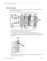
Cable connections to the FT server are made on the rear of the unit to the backplane and to both
CPU/IO modules as described here.
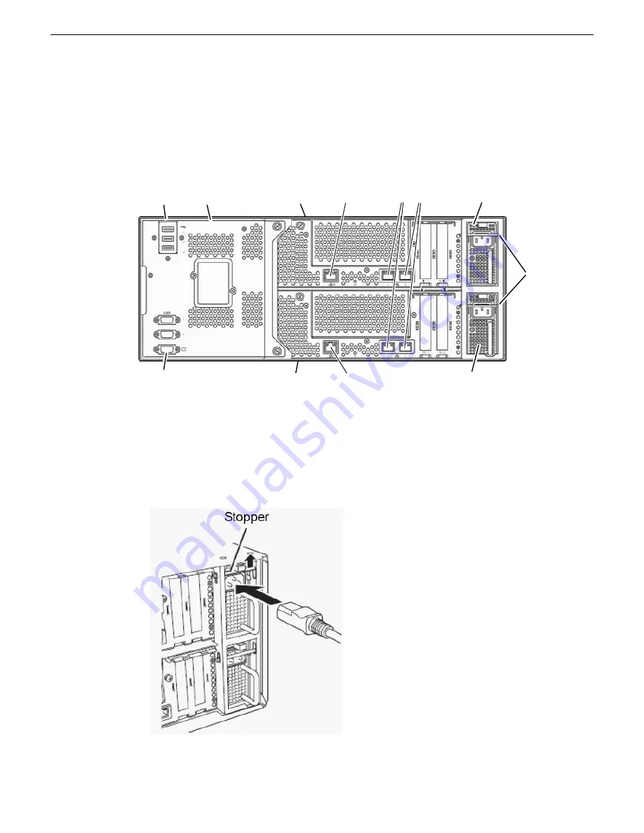
Refer to the illustration of the rear module and its cable connections below.
CPU/IO module 0
power supply
CPU/IO module 1
power supply
Management
LAN for CPU/IO 1
Management
LAN for CPU/IO 0
Teamed
Duplex LANs
3 USB ports
VGA connector
CPU/IO
module 0
CPU/IO
module 1
Backplane
AC cord
stopper
bars
1. Connect a mouse and keyboard to the USB connections on the backplane.
2. Connect a flat screen to the bottom VGA serial connector.
3. Connect the AC cords to each of the CPU/IO AC receptacles but do not power up.
Notice that when the AC cord is inserted, the AC Stopper bars will engage as shown below. The
Stopper bars prevent you from removing a CPU/IO module with the AC cord connected (while
powered up).
4. The Teamed Duplex LANs connect the FT server to the network as appropriate for the FT server's
use as a Grass Valley system device.
26
FT Server Instruction Manual
20131220
FT Server Installation Information
Summary of Contents for FT
Page 1: ...Fault Tolerant Server Platform FT Server Instruction Manual 071 8852 03 20131220 ...
Page 2: ......
Page 3: ...Fault Tolerant Server Platform FT Server Instruction Manual 071 8852 03 20131220 ...
Page 4: ......
Page 36: ...36 FT Server Instruction Manual 20131220 FT Server Installation Information ...
Page 42: ...5 Click OK 42 FT Server Instruction Manual 20131220 Configuring the FT Server ...
Page 90: ...90 FT Server Instruction Manual 20131220 Servicing the FT Server ...
Page 94: ...94 FT Server Instruction Manual 20131220 Trademarks and Agreements ...


