24
Environment and Location
Control Surfaces
Control Surfaces
Mounting a Kula Control Surface into a Desk
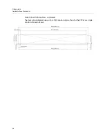
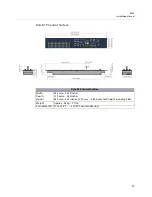
With the desk cut to the correct size, desk cut-out information can be found on:
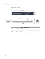
• 24 crosspoint (KPX and K1X) cutout diagrams on pages 37 and 38.
• 16 crosspoint (K1P and KPP) cutout diagrams on page 41.
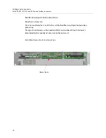
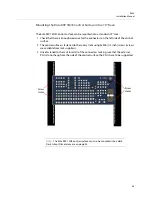
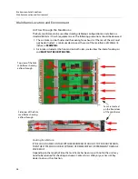
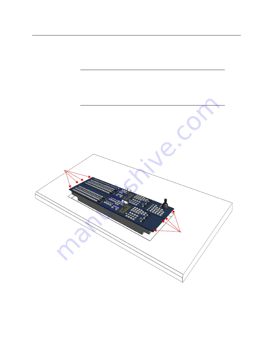
The Control Surface is secured into a desk using appropriate “Pan Head” M4 screws with a
Max. head diameter of 8.8mm [0.34 Inches]. At each end of each Control Surface, there are
two 4.5 mm [0.18 Inches] fixing point holes for the screws (as shown on the diagram below).
Note:
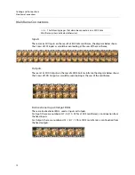
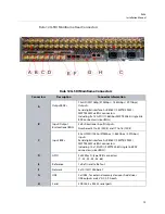
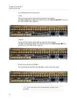
The Kula control surface should preferably be mounted in a desk
which is open underneath.
Note:
If the desk is not open underneath, enough room has to be left
underneath for ventilation and for routing the PSU and Comms cables to the
underside of the control surface.
Note:
It is essential to ensure the air temperature does not exceed 40°C.
Fixing point
Screw Holes
Fixing point
Screw Holes
Summary of Contents for KULA
Page 1: ...Installation Manual Issue 5 Rev 1 2020 10 29 KULA PRODUCTION SWITCHER ...
Page 16: ...xvi Notices ...
Page 20: ...2 Introduction About this Manual ...
Page 40: ...22 Cabling and Connections Mainframe Connections ...
Page 50: ...32 Environment and Location Ancillary Panels ...
Page 61: ...43 Kula Installation Manual Desk Cutout Dimensions for K5P 1M E 19 Control Surface ...

