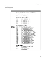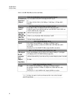
background image

40

Dimensions

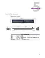
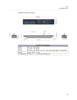
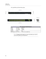
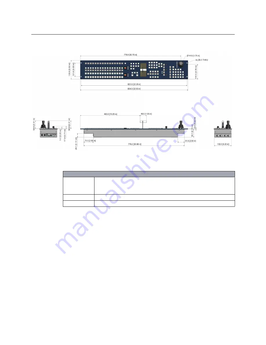
Control Surface Dimensions

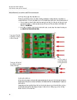
Kula KPP Control Surface

Kula KPP Control Surface

Width
Depth
Height

834 mm ~ 32.83 Inches
139.8mm ~ 5.50 Inches
64.7mm ~ 2.55 Inches (123.3 mm ~ 4.86 Inches total height including T-Bar)

Weight

Approx - 4.0kg ~ 8.81lb

Environmental

41 to 104°F

~ 5 to 40°C non-condensing

Summary of Contents for KULA

Page 1: ...Installation Manual Issue 5 Rev 1 2020 10 29 KULA PRODUCTION SWITCHER ...

Page 2: ...ts For further information please visit www grassvalley com patents Copyright and Trademark Notice Grass Valley GV and the Grass Valley logo and or any of the Grass Valley products listed in this document are trademarks or registered trademarks of GVBB Holdings SARL Grass Valley USA LLC or one of its affiliates or subsidiaries All other intellectual property rights are owned by GVBB Holdings SARL ...

Page 3: ...thout notice and does not represent a commitment on the part of Grass Valley Warranty information is available from the Legal Terms and Conditions section of Grass Valley s website www grassvalley com Important Safety Information This section provides important safety guidelines for operators and service personnel Specific warnings and cautions appear throughout the manual where they apply Please ...

Page 4: ...electric shock The presence of this symbol in or on Grass Valley equipment means that it has been tested and certified as complying with applicable Underwriters Laboratory UL regulations and recommendations for USA The presence of this symbol in or on Grass Valley equipment means that it has been tested and certified as complying with applicable Canadian Standard Association CSA regulations and re...

Page 5: ...this product or on the equipment To avoid explosion do not operate this equipment in an explosive atmosphere Use proper lift points Do not use door latches to lift or move equipment Avoid mechanical hazards Allow all rotating devices to come to a stop before servicing Have qualified service personnel perform safety checks after any service Cautions A caution indicates a possible hazard to equipmen...

Page 6: ...t of the chassis For safety periodically check the resistance value of the antistatic strap which should be between 1 and 10 megohms When temporarily storing a card make sure it is placed in an ESD bag Cards in an earth grounded metal frame or casing do not require any special ESD protection Battery Handling This product may include a backup battery There is a danger of explosion if the battery is...

Page 7: ...éférence dans le texte doit être remplacé par un fusible du même calibre Identifie une borne de mise à la terre de protection Il faut relier cette borne à la terre avant d effectuer toute autre connexion à l équipement Identifie une borne de mise à la terre externe qui peut être connectée en tant que borne de mise à la terre supplémentaire Signale la présence de composants sensibles à l électricit...

Page 8: ...alimentation avant de nettoyer l équipement Ne pas utiliser de nettoyants liquides ou en aérosol Utilisez uniquement un chiffon humide Des tensions dangereuses peuvent exister en plusieurs points dans cet équipement Pour éviter toute blessure ne touchez pas aux connexions ou aux composants exposés lorsque l appareil est sous tension Avant de procéder à toute opération d entretien ou de dépannage e...

Page 9: ...on N utilisez pas l équipement si vous suspectez un dysfonctionnement du produit Faites le inspecter par un technicien qualifié Pour réduire le risque de choc électrique n effectuez pas de réparations autres que celles qui sont décrites dans le présent manuel sauf si vous êtes qualifié pour le faire Confiez les réparations à un technicien qualifié La maintenance doit se réaliser dans un milieu lib...

Page 10: ...ez la pile uniquement par un modèle identique ou équivalent recommandé par le fabricant Disposez des piles usagées conformément aux instructions du fabricant Avant de vous séparer de votre équipement Grass Valley veuillez consulter les informations de mise au rebut et de recyclage à http www grassvalley com assets media 5692 Take Back_Instructions pdf Précautions pour les écrans LCD et TFT Regarde...

Page 11: ...alley equipment usually comes with at least one button battery located on the main printed circuit board The batteries are used for backup and should not need to be replaced during the lifetime of the equipment Battery Disposal Before disposing of your Grass Valley equipment please remove the battery as follows 1 Make sure the AC adapter power Cord is unplugged from the power outlet 2 Remove the p...

Page 12: ...a fire as they may explode Batteries may explode if damaged or overheated Do not dismantle open or shred batteries In the event of a battery leak do not allow battery liquid to come in contact with skin or eyes Seek medical help immediately in case of ingestion inhalation skin or eye contact or suspected exposure to the contents of an opened battery ...

Page 13: ... the beam should be treated with caution and common sense because it is intense and concentrated Laser radiation can cause irreversible and permanent damage of eyesight Please read the following guidelines carefully Make sure that a fiber is connected to the board s fiber outputs before power is applied If a fiber cable e g patchcord is already connected to an output make sure that the cable s oth...

Page 14: ...netic Compatibility Limits for harmonic current emissions EN61000 3 3 2013 Electromagnetic Compatibility Limits of voltage changes voltage fluctuations and flicker EN55103 2 2009 Environment E2 Electromagnetic Compatibility Product family standard for audio video audio visual and entertainment lighting control apparatus for professional use Part 2 Immunity FCC CFR 47 Part 15 Class A Federal Commun...

Page 15: ...tions shall be made with high quality double screened coaxial cables such as Belden 8281 or BBC type PSF1 2M and Belden 1694A for 3Gbps D TYPE CONNECTORS D type connectors shall have metal shells making good RF contact with the cable screen Connectors having dimples which improve the contact between the plug and socket shells are recommended Note This equipment has been tested and found to comply ...

Page 16: ...xvi Notices ...

Page 17: ...1 About this Manual 1 2 Cabling and Connections 3 Kula KPX KPP K1X K1P and K5P Control Surface Connectors 3 Connecting the Touch Screen Monitor GUI 6 Kula K1X and K1P Connections 7 Connecting a 2M E Control Surface together 8 Mainframe Layout and Connections 10 Mainframe Connections 12 Inputs 12 Outputs 12 Bi directional Input Output BNCs 12 Kula 12G SDI Mainframe Rear Connectors 13 12G SDI Mainfr...

Page 18: ...ies 34 5 Dimensions 35 Control Surface Dimensions 35 Kula KPX Control Surface 35 Kula K1X Control Surface 36 Desk Cutout Information for KPX and K1X Control Surfaces 37 Kula K1P Control Surface 39 Kula KPP Control Surface 40 Desk Cutout Information for KPP and K1P Control Surfaces 41 Kula K5P 1M E 19 Control Surface 42 Mainframe Dimensions 44 Kula Mainframe 44 Ancillary Panels 45 Mav Remote Dimens...

Page 19: ... to the contact details listed at the rear of this manual 3M E 24 Xpt Comprised of 1x K1X control surface 1x K1X control surface 1x KPX control surface 2M E 24 Xpt Comprised of 1x K1X control surface 1x KPX control surface 2M E 16 Xpt Comprised of 1x K1P control surface 1x KPP control surface 1M E 19 K5P Control Surface Kula Mainframe Note Please note that all diagrams are for illustration purpose...

Page 20: ...2 Introduction About this Manual ...

Page 21: ...mms to the Kula K1X and K1P control surfaces 2x Comms Ports Network Port to Mainframe 2x USB Connectors 2x External PSU Connectors 1 2 3 4 5 Monitor Out 1 2 3 4 5 4x Comms Ports 6 6 1 2 3 4 5 Kula K5P 1M E 19 Control Surface Kula KPP Kula K1P 5 and Kula KPX and Kula K1X Note Only two of the Comms ports on the KPX and KPP control surface are required to connect to the K1P control surface they also ...

Page 22: ...ed Diagram below shows the connector information for KPX KPP and K5P Control Surfaces LH Side 1 2 3 4 5 Note The label below is on the underside of the control surface Diagram below shows the connector information for KPX and KPP Control Surface RH Side Note The label below is on the underside of the control surface 6 ...

Page 23: ... 2 Connectors 3 Monitor MON Output to touch screen GUI 4 10 100 1000 base T RJ45 network connectors to the switcher mainframe 5 2x Comms Connection Important Note NOT Ethernet connections must be direct to a control surface Do Not use network switches or hubs CAT5 or above cables crossover cables are Not suitable 6 4x Comms Connection See Important Note above ...

Page 24: ... the monitor be larger than 21 inches Touch screen monitor once the external monitor is connected to the Kula control surface a USB control lead shown above is connected allowing the touch screen functions to be used Silk Screen from the side of the Control surface MON monitor output port KPP or KPX Note the K5P control surface is connected in exactly the same way MON monitor output port USB port ...

Page 25: ...1X and K1P Connections The Kula K1X and K1P provides a 1 M E Control Surface that works with the KPP Program Preview control surface All power and comms to the control surface are provided by the KPP control surface Diagram below shows the connector information for K1X and K1P Control Surface RH Side Note The label below is on the underside of the control surface 2x Comms Connection Important Note...

Page 26: ...s a diagram showing how to connect a KPX and a K1X control surface together Connect the KPX control surface to the K1X control surface via the two Comms ports on the right hand side of the control surface Kula KPX Control Surface Kula K1X Control Surface Kula K1X Kula KPX Note Two Comms cables must be connected for correct operation ...

Page 27: ...ces together Connect the KPX control surface to the 2x K1X control surfaces via the two Comms ports on the right hand side of the control surface Kula KPX Control Surface 2x Kula K1X Control Surface Kula K1X Kula K1X Kula KPX Note The two Comms cables on each K1X control surface must be connected to the KPX control surface for correct operation ...

Page 28: ...nd Connections Mainframe Overview The Kula mainframe has 1 card that has all the Mix Effects and Input Output video processing The type of mainframe i e the number of M Es and number of Inputs Outputs is determined by the number of sub cards on the main card Kula Mainframe Front Card Location Main Card ...

Page 29: ...nal BNCs 4x SDI SDO BNC Inputs plus 2x Bi Directional Input Outputs Numbered 37 to 42 2M E and 13 to 18 1M E C GPIO 3x 25 Way D type GPIO connectors 1 22 23 44 45 66 D Reference 1x Ref In and 1x Ref out E Network 3x 10 100 1000 base T F USB 2x USB3 for external memory device or hard drives USB outputs are 5 V DC 0 9 A each G Serial 2X RJ45 RS422 Ethernet ports H Inputs 36x SDI BNC numbered BNC 1 t...

Page 30: ...mainframe the diagram below shows the 2 rows of SDO Outputs as would be seen looking at the rear of the mainframe Bi directional Input Output BNCs These are bi directional BNCs used as Inputs or Outputs For Inputs these are numbered 37 42 19 24 for a 1M E mainframe a continuation from the fixed inputs For Outputs these are numbered 13 18 7 12 for a 1M E mainframe a continuation from the fixed outp...

Page 31: ... BNCs B Input Output Bi directional BNCs 2x Bi Directional Input Outputs Numbered 41 to 42 2M E and 17 to 18 1M E C Input BNCs 40 x HD SD 1080p 270Mbps 1 485Gbps 2 97Gbps Inputs Serial digital interface As REC601 SMPTE 292M SMPTE424M via BNC connectors Including 10 x 12G SDI SMPTE 2082 single link BNC connectors silver BNCs D GPIO 3x 25 Way D type GPIO connectors 1 22 23 44 45 66 E Reference 1x Re...

Page 32: ...Cs are inputs for 12G SDI SMPTE 2082 single link Outputs There are 12x SDI Outputs in total that can output SD HD and 1080p 270Mbps 1 485Gbps 2 97Gbps Three of those outputs with silver colored BNCs are outputs for 12G SDI SMPTE 2082 single link Bi directional Input Output BNCs These are bi directional SD HD and 1080p BNCs used as Inputs or Outputs Note Inputs and Outputs will vary depending on th...

Page 33: ... Input Outputs Numbered 41 to 42 2M E and 17 to 18 1M E C Input BNCs 4 x HD SD 1080p 270Mbps 1 485Gbps 2 97Gbps Inputs Serial digital interface As REC601 SMPTE 292M SMPTE424M via BNC connectors Including 1 x 12G SDI SMPTE 2082 single link BNC connectors silver BNC D GPIO 3x 25 Way D type GPIO connectors 1 22 23 44 45 66 E Reference 1x Ref In and 1x Ref out F Network 3x 10 100 1000 base T G USB 2x ...

Page 34: ... links Each 50GbE link transports 3x SMPTE 2022 6 or VSF TR 03 SMPTE 2110 SD HD 1080p outputs Inputs A2 and B2 1x 50GbE each Secondary QSFP connection A2 is on the upper A card and B2 is on the lower B card Inputs 18x on each Secondary 50GbE QSFP SMPTE 2022 6 or VSF TR 03 SMPTE 2110 SD HD 1080p inputs across two 50GbE links Each 50GbE link transports 9 x SMPTE 2022 6 or VSF TR 03 SMPTE 2110 SD HD ...

Page 35: ...utput 12x Primary Outputs Total SMPTE 2022 6 or VSF TR 03 SMPTE 2110 SD HD 1080p outputs across two 50GbE links Each 50GbE link transports 3x SMPTE 2022 6 or VSF TR 03 SMPTE 2110 SD HD 1080p outputs 2x 50GbE A2 B2 are the Secondary QSFP Input and Output connections for the Upper A and Lower B card giving redundancy Input BNCs 4 x HD SD 1080p 270Mbps 1 485Gbps 2 97Gbps Inputs Serial digital interfa...

Page 36: ...erent functions depending on the type communication they are receiving the list below describes the functions Connectors with XLR shells can be used to connect with these network connectors In each case LED Lit link Flashing traffic Left LED Right LED 1G bit 1000 base T GREEN GREEN 100Mbit 100baseT OFFGREEN 10Mbit 10baseT YELLOWGREEN No link OFF OFF Reference Analogue reference input and output No...

Page 37: ... 8 GPO13 8 GPO 35 8 GPO 57 9 GPO 15 9 GPO 37 9 GPO 59 10 GPO17 10 GPO 39 10 GPO 61 11 GND 11 GND 11 GND 12 GPO 20 12 GPO 42 12 GPO 64 13 GPO 22 13 GPO 44 13 GPO 66 14 GPO 1 14 GPO 23 14 GPO 45 15 GPO 3 15 GPO 25 15 GPO 47 16 GPO 5 16 GPO 27 16 GPO 49 17 GPO 7 17 GPO 29 17 GPO 51 18 GPO 9 18 GPO 31 18 GPO 53 19 GPO 10 19 GPO 32 19 GPO 54 20 GPO 12 20 GPO 34 20 GPO 56 21 GPO 14 21 GPO 36 21 GPO 58 2...

Page 38: ...aster settings makes Kula able to control external equipment and a Slave setting lets Kula be controlled by external equipment RS422 1 3 Pin Configuration RJ45 Pin Color typical Function master mode 9 pin D Type SP1 9 pin D Type SP3 1 Orange White Tx1B 3 2 Orange Tx1A 8 3 Green White Tx3B 3 4 Blue Tx3A 8 5 Blue White RX3A 2 6 Green RX3B 7 7 Brown White Rx1A 2 8 Brown Rx1B 7 Cable screen GND GND 9 ...

Page 39: ...n White Rx2A 2 8 Brown Rx2B 7 Cable screen GND GND 9 9 Pin Master Slave 1 Ground Ground 2 Rx A Tx A 3 Tx B Rx B 4 Tx Common Rx Common 5 Spare Spare 6 Rx Common Tx Common 7 Rx B Tx B 8 Tx A Rx A 9 Ground Ground RS422 2 4 Pin Configuration RJ45 Pin Color typical Function master mode 9 pin D SP2 9 pin D SP4 ...

Page 40: ...22 Cabling and Connections Mainframe Connections ...

Page 41: ...rack environments Attention should be paid to the cooling information for the mainframe The ambient temperature for all the supplied equipment should not exceed the limits of 5 and 40 C 41 to 104 F at a relative humidity of 10 to 90 non condensing Installing the equipment in a clean environment with moderate temperature and humidity will promote a long and trouble free equipment life ...

Page 42: ...crews with a Max head diameter of 8 8mm 0 34 Inches At each end of each Control Surface there are two 4 5 mm 0 18 Inches fixing point holes for the screws as shown on the diagram below Note The Kula control surface should preferably be mounted in a desk which is open underneath Note If the desk is not open underneath enough room has to be left underneath for ventilation and for routing the PSU and...

Page 43: ... control surface 2 The control surface is fastened to the rack system using 4x M6 1 4 inch screws screws are available from rack suppliers 3 Once fastened to the rack insert all of the connectors making sure that the external PSUs do not hang from the side of the control surface the PSUs have to be supported Note The Kula K5P 1M E control surface can also be mounted into a desk Desk Cutout Dimensi...

Page 44: ...s is ESSENTIAL 2 Air intakes situated at the front and on both sides are to allow the inlet of cooling air and MUST NOT BE OBSTRUCTED Cooling Fan Failure IF THE COOLING FANS ONTHE SWITCHER MAINFRAME SHOULD STOP FOR ANY REASON THEN THE SYSTEM SHOULD BE SWITCHED OFF IMMEDIATELY OR PERMANENT DAMAGE MAY RESULT Depending on the length of time the mainframe has been run with no fan the unit may need to ...

Page 45: ... Manual Warning Note Do not obstruct air intakes to fans and air vents on any piece of equipment listed in this manual Please pay particular attention to the air intakes at sides and the vents at the rear of the Mainframe ...

Page 46: ...me front door will have to be opened To do this unscrew the door locking screws on either side of the door then pull outwards and lower as shown in the diagram below 5 The mainframe is fastened to the rack system using 4x M6 1 4 inch screws screws are available from rack suppliers Note The Kula Mainframe is heavy 14kg 30 3lb and will require two people to lift into position using correct lifting p...

Page 47: ...a joining plate Desk Mount The rack mount ear mounting brackets can be set to two different positions horizontal with the mounting holes facing upwards and vertically for Rack Mount as described in the 19 Rack Mount description this will allow the unit to be secured to the underside of a desk With the rack mount ears in the horizontal position the unit can be secured to a desk using 4x screws Moun...

Page 48: ... to the rack sides 19 Rack Mount using two Mav Remote units with a Joining Plate Two Mav Remote units can be joined together using a joining plate which allows the units to span across the full width of the rack and fasten to the rack without the support of a rack tray Note The Mav Remote must have ventilation to allow cooling and must not be installed into an enclosed space The unit is secured to...

Page 49: ...19 rack is exactly the same for both Aux panels The ears of the Aux Panels have 2x holes on each side use the correct rack mount screws and fixings in the 4x mounting holes to secure the Aux panel to the rack as shown below Make sure that enough access is allowed behind the Aux panel to connect the external PSU and network cable ...

Page 50: ...32 Environment and Location Ancillary Panels ...

Page 51: ...C Power Cables are plugged into the IEC connectors and turned On at the AC mains supply Checking the Kula Power Supplies Kula mainframe power supplies are hot swappable Replacing power supplies should only be attempted by qualified personnel To see that the power supplies are working correctly when mains power is applied a green power LED is lit as shown below With the power supplies un plugged fr...

Page 52: ...her is for redundancy Caution The Power Supplies have NO user serviceable parts inside and are welded shut Do not attempt to open the power supply cases The power supply connector plug that connects to the control surface is a 4 pin Snap and Lock type care should be taken when connecting and un connecting Note Make sure that the mains power is turned Off before connecting the PSU to the control su...

Page 53: ...PX Control Surface Kula KPX Control Surface Width Depth Height 994 mm 39 13 Inches 139 8mm 5 50 Inches 64 7mm 2 55 Inches 123 3 mm 4 86 Inches total height including T Bar Weight Approx 5Kg 11 02lb Environmental 41 to 104 F 5 to 40 C non condensing ...

Page 54: ...1X Control Surface Kula K1X Control Surface Width Depth Height 994 mm 39 13 Inches 139 8mm 5 50 Inches 64 7mm 2 55 Inches 123 3 mm 4 86 Inches total height including T Bar Weight Approx 4 2Kg 9 25lb Environmental 41 to 104 F 5 to 40 C non condensing ...

Page 55: ...or KPX and K1X Control Surfaces The desk cutout diagram below is for a 3M E control surface this is the KPX and 2x K1X control surfaces combined The desk cutout diagram below is for a 2M E control surface this is the KPX and K1X control surfaces combined ...

Page 56: ...38 Dimensions Control Surface Dimensions Desk Cutout Information continued The desk cutout diagram below is for a 1M E control surface this is for the KPX or as a single control surface on its own ...

Page 57: ...m shows the end view of a Row Kula K1P Control Surface Width Depth Height 834 mm 32 83 Inches 139 8mm 5 50 Inches 64 7mm 2 55 Inches 123 3 mm 4 86 Inches total height including T Bar Weight Approx 3 5Kg 7 71lb Environmental 41 to 104 F 5 to 40 C non condensing ...

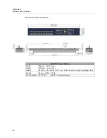
Page 58: ...PP Control Surface Kula KPP Control Surface Width Depth Height 834 mm 32 83 Inches 139 8mm 5 50 Inches 64 7mm 2 55 Inches 123 3 mm 4 86 Inches total height including T Bar Weight Approx 4 0kg 8 81lb Environmental 41 to 104 F 5 to 40 C non condensing ...

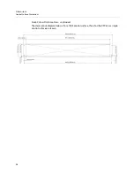
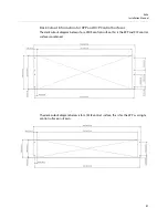
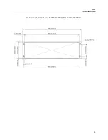
Page 59: ...KPP and K1P Control Surfaces The desk cutout diagram below is for a 2M E control surface this is the KPP and K1P control surfaces combined The desk cutout diagram below is for a 1M E control surface this is for the KPP as a single control surface on its own ...

Page 60: ...E 19 Control Surface Kula K5P 1M E Control Surface Width Depth Height 482 6 mm 19 Inches 221 5mm 8 72 Inches 87 9mm 3 46 Inches 146 5 mm 5 79 Inches total height including T Bar Weight Approx 3 6Kg 7 14lb Environmental 41 to 104 F 5 to 40 C non condensing ...

Page 61: ...43 Kula Installation Manual Desk Cutout Dimensions for K5P 1M E 19 Control Surface ...

Page 62: ...frame Dimensions Mainframe Dimensions Kula Mainframe Kula Mainframe Width Depth Height 482 6 mm 19 Inches 604 8mm 23 81 Inches 87mm 3 42 Inches Weight Approx 14Kg 30 3lb Environmental 41 to 104 F 5 to 40 C non condensing ...

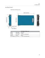
Page 63: ... Ancillary Panels Mav Remote Dimensions Mav Remote Dimensions Width Depth Height 9 44 inches 239 9 mm 12 95 inches 329 mm 2 00 inches 50 7 mm including feet Weight TBC lbs TBCkg Environmental 41 to 104 F 5 to 40 C non condensing ...

Page 64: ...Aux Panel Dimensions Width Depth Height 19 inches 482 6mm 1 51 inches 38 4mm 1 72 inches 43 6 mm Weight 2 2 lbs 1kg Environmental 41 to 104 F 5 to 40 C non condensing Note The diagram above displays the LCD Aux Panel dimensions The LED Aux Panel has exactly the same dimensions ...

Page 65: ...s are Not suitable Kula K1X and K1P Control Surface Power and Comms Description Connections to the KPX and KPP Control Surface 2x RJ45 connectors for Comms and 12V 0 42A power supply in from the KPP control surface NOT Ethernet connections must be direct to the control surface Do Not use network switches or hubs CAT5 or above cables crossover cables are Not suitable Kula K5P Control Surface Connec...

Page 66: ...lly independent external PSU modules with separate mains power feeds via 2x 10A IEC leads Output from each PSU 12V DC 100W via Kycon KPPX 4 Pin or Compatible connectors to the KPX and KPP control surface 2 supplied as standard 2 PSUs provide dual redundancy External Mains Power Supply Requirements Voltage 100V 240V 50 60Hz Power Less than 120 Watts ...

Page 67: ...PTE 274M 6 292M F 1035i 60Hz ANSI SMPTE 260M 292M A 1035i 59 94Hz ANSI SMPTE 260M 292M B 1080p 30Hz sF ANSI SMPTE 274M 12 as per RP211 1080p 29 97Hz sF ANSI SMPTE 274M 13 as per RP211 1080p 25Hz sF ANSI SMPTE 274M 14 as per RP211 1080p 24Hz sF ANSI SMPTE 274M 15 as per RP211 1080p 23 976Hz sF ANSI SMPTE 274M 16 as per RP211 1080p 30Hz ANSI SMPTE 274M 7 292M G 1080p 29 97Hz ANSI SMPTE 274M 8 292M H...

Page 68: ... Key Input Output Rates 3G 148 50 MHz or 148 50 1 001 MHz HD 74 25 MHz or 74 25 1 001 MHz SD 13 5MHz Pb Pr Input Output Rates 3G 74 25 MHz or 74 25 1 001 MHz 4 2 2 HD 37 125 MHz or 37 125 1 001 MHz 4 2 2 SD 6 75MHz Synchronization Input line synchronizers on all paths ...

Page 69: ...rial digital interface as per ANSI SMPTE 259 292M Analogue HD Reference 300mV tri level sync 6dB Analogue SD Reference 300mV sync with optional 300mV pk pk burst 6dB Impedance 75 ohms except reference input Mainframe Bi directional Inputs Outputs Bi directional Inputs and Outputs 2x Tri standard SD SDI HD SDI 3Gbps SDI BNC Inputs only or 2x 1080p SDI HD SDI SD SDI 270Mbps 1 485Gbps 2 97Gbps BNC Ou...

Page 70: ...pt reference input Kula 12G SDI Mainframe Inputs Inputs 40 x HD SD 1080p 270Mbps 1 485Gbps 2 97Gbps Inputs Serial digital interface As REC601 SMPTE 292M SMPTE424M via BNC connectors Including 10 x 12G SDI SMPTE 2082 single link BNC connectors Kula 12G SDI Mainframe Output Formats Levels SDI Output Format Tri Standard 3Gbps SDI HD SDI SD SDI 1080p 270Mbps 1 485Gbps 2 97Gbps and 12G SDI SMPTE 2082 S...

Page 71: ...oss two 50GbE links Each 50GbE link transports 9 x SMPTE 2022 6 or VSF TR 03 SMPTE 2110 SD HD 1080p inputs Outputs A2 and B2 6 x on each secondary QSFP SMPTE 2022 6 or VSF TR 03 SMPTE 2110 SD HD 1080p outputs across two 50GbE links Each 50GbE link transports 3 x SMPTE 2022 6 or VSF TR 03 SMPTE 2110 SD HD 1080p outputs Note A2 and B2 Secondary are for redundancy Kula IP Mainframe Input BNCs Input B...

Page 72: ...54 Specifications Kula Mainframe Bi directional Inputs and Outputs 2x Tri standard SD SDI HD SDI 3Gbps SDI BNC Inputs or 2x 1080p SDI HD SDI SD SDI 270Mbps 1 485Gbps 2 97Gbps BNC Outputs ...

Page 73: ... 2x USB 2 Connectors Network 1x 10 100 1000 base T Auto MDX MDXI on RJ45 connectors Connections to MAV modules 8x RJ45 connectors for Comms and 2x 12V 0 42A power supply Connection to other MAV modules NOT Ethernet connections must be direct to MAV modules Do Not use network switches or hubs CAT5 or above cables crossover cables are Not suitable Mav Remote Power Supplies Power Supply Description T...

Page 74: ...lies Mainframe Two fully independent hot swappable PSU modules with separate mains power feeds via 2 x IEC sockets Dual Redundant requires two fully independent PSU modules with separate mains power feeds via 2 x IEC socket Mainframe Power Supply Requirements Voltage 100V 240V 50 60Hz 5 2A Power 400 Watts Max ...

Page 75: ...in a local phone number for the support center nearest you please consult the Contact Us section of Grass Valley s website www grassvalley com An online form for e mail contact is also available from the website Corporate Head Office Grass Valley 3499 Douglas B Floreani St Laurent Quebec H4S 2C6 Canada Telephone 1 514 333 1772 Fax 1 514 333 9828 www grassvalley com ...

Reviews: