Chapter 1 About the PFC500/E
18
PFC 500/E Instruction Manual
2 December 1999
PFC500/E components
The PFC 500/E components are:
• A sheet-metal chassis with a midplane and front door
• One or two RAID controllers (PFC500 only)
• One or two Link Control cards (PFC500E only)
• As many as ten Fibre Channel disk modules
• One or two power supplies
• One drive fan pack
Any unoccupied slot (RAID controller, disk module, or power supply) has a filler
module to maintain air flow and compliance with electromagnetic interference (EMI)
standards.
The RCs, disk modules, power supplies, fan packs, and filler modules are
customer-replaceable units (CRUs), which you can add or replace without tools while
the PFC500/E is powered up.
The optional high availability features for an PFC500/E are
• second RC (PFC500 only)
• second power supply
A second RC provides continued access to the PFC500 and any connected PFC500Es
if the first RC fails. Adding a second RC to the same chassis is not intended to increase
performance, but rather to add redundancy
.
Refer to the Profile XP System Guide for
detailed connection, configuration, and performance information.
The disk drives are FC-AL compliant and support dual-port FC-AL interconnects
through the two RCs and their cabling.
Chassis
The chassis is a sheet-metal housing with a front panel, a midplane, front door, and
slots for the RCs, disk modules, power supplies, and the fan pack.
The following figures show the PFC500/E components. Details on each component
follow the figures. If the chassis provides slots for two identical components, the
component in slot A is called component-name A. If there is a second component, it
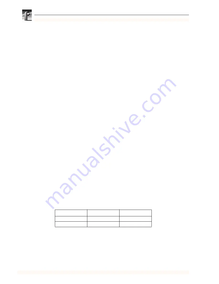
is in slot B and is called component-nameB, as follows.
If you have one power supply, it can be in either slot A or slot B. If you have one
RAID controller, it can be in either slot A or B.
Component
Name in slot A
Name in slot B
RAID Controller
RC A
RC B
Power supply
PS A
PS B


