background image

Chapter 3    Servicing and upgrading a PFC 500/E   

62

PFC 500/E Instruction Manual

2 December 1999

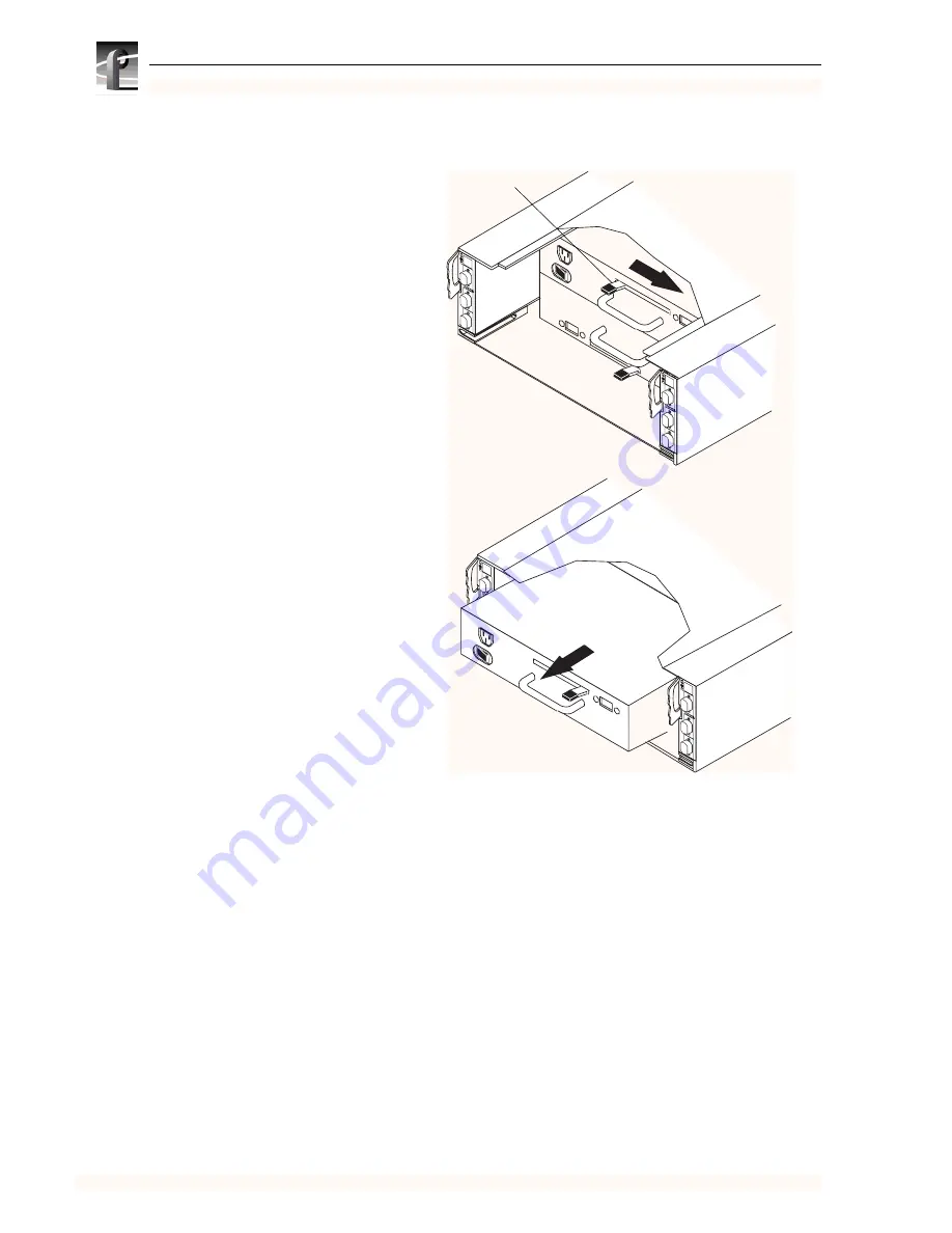
3. Remove the power supply as shown here.

A

B

EX

P

A

B

EX

P

A

B

EX

P

A

B

EXP

A. With your thumb, push the latch 

up, and then right as far as it 
goes.

You may need to brace your 
hand against the supply’s 
handle.

B. Grasp the handle with one hand, 

and gently pull the supply from the 
chassis, supporting it with your 
other hand.

Latch

Summary of Contents for PROFILE XP PFC 500/E

Page 1: ... Gr ass Valley Group Inc PO Box 1114 Gr ass Valley CA 95945 USA 530 478 4148 htt p www grassvalleygroup com Instruction Manual P R O F I L E X P P F C 5 0 0 E F I B R E C H A N N E L R A I D S T O R A G E S Y S T E M ...

Page 2: ...ile and Profile XP are registered trademarks of Grass Valley Group Inc Other trade names used in this document are trademarks or registered trademarks of the manufacturers or vendors of the associated products Grass Valley Group License Agreement Profile system software contains intellectual property of Grass Valley Group Inc i e software programs that are licensed for use by the end user consumer...

Page 3: ...Under this license Buyer and Buyer is authorized and Buyer agrees to do only the following 1 Execute the Code only on the Machine as necessary to operate or maintain the Machine according to its specifications except that utility software designated as such may be executed on a host connected to the Machine but only for use with the Machine and 2 make a backup or archival copy of the Code which Bu...

Page 4: ...4 PFC 500 E Instruction Manual 2 December 1999 ...

Page 5: ...es 22 Disk drives 22 Drive carrier 22 Power supplies PSs 23 Drive fan pack 24 Configurations 24 What next 24 Chapter 2 Installing a PFC500 E Requirements 25 Site requirements 25 Power 25 Cooling 25 Cabling requirements 26 Addressing requirements 26 FC AL address ID 26 Chassis address CA 26 Installing a PFC500 E in a cabinet 27 Determining the rail mounting positions 27 Attaching the mounting rails...

Page 6: ... Installing an RC or an RC filler module 54 Replacing the drive fan pack 57 Replacing or adding a power supply module 59 Appendix A Technical specifications and operating limits Technical specifications 67 ac power requirements 67 Size and weight 68 Drive type 68 Disk module address 68 RC FC AL interface 68 Copper cabling 69 Standards certification and compliance 69 Safety standards 69 EMI standar...

Page 7: ...r output terminals of the product ensure that the product is properly grounded Do Not Operate Without Covers To avoid electric shock or fire hazard do not operate this product with covers or panels removed Do Not operate in Wet Damp Conditions To avoid electric shock do not operate this product in wet or damp conditions Do Not Operate in an Explosive Atmosphere To avoid injury or fire hazard do no...

Page 8: ...arking CAUTION indicates a hazard to property including the product Symbols on the Product The following symbols may appear on the product DANGER high voltage Protective ground earth terminal ATTENTION refer to manual Service Safety Summary Do Not Service Alone Do not perform internal service or adjustment of this product unless another person capable of rendering first aid and resuscitation is pr...

Page 9: ...nt Canadian EMC Notice of Compliance This digital apparatus does not exceed the Class A limits for radio noise emissions from digital apparatus set out in the Radio Interference Regulations of the Canadian Department of Communications Le présent appareil numérique n émet pas de bruits radioélectriques dépassant les limites applicables aux appareils numériques de la classe A préscrites dans le Règl...

Page 10: ...to comply with certain regulatory requirements pertaining to Information Technology Equipment This product has not been designed for use as a medical device Without limitation of the foregoing this product is not intended and has not been certified for use in a hospital or clinical environment to diagnose treat or monitor patients under medical supervision and is not intended and has not been cert...

Page 11: ...i l e X P M a n u a l F a m il y o f X P S e r ie s G r a s s V a l l e y G r o u p P r o f i l e X P M a n u a l F a m il y o f X P S e r ie s G r a s s V a l l e y G r o u p 0624 39 P r o f i l e X P M a n u a l F a m il y o f X P S e r ie s G r a s s V a l l e y G r o u p P r o f i l e X P M a n u a l F a m il y o f X P S e r ie s G r a s s V a l l e y G r o u p Release Notes Path for the Insta...

Page 12: ...P Media Platform into your operation Profile XP User Manual Contains complete instructions for using Profile applications to operate the Profile XP Media Platform Profile XP Service with NetCentral Manual Contains information for servicing the Profile XP Media Platform and includes procedures for the following tasks Problem analysis using symptom problem solution tables Running diagnostics locally...

Page 13: ...s PFC500 and the RAID Expansion Chassis PFC500E You can read this chapter to get familiar with the RAID Storage Chassis key features and components Chapter 2 Installing a PFC500 E Describes how to install a RAID Storage Chassis and RAID Expansion Chassis including rack mounting Refer to the Profile XP System Guide for connection and configuration information Chapter 3 Servicing and upgrading a PFC...

Page 14: ... Electronic versions of the following manuals are located on the system drive of your Profile XP Media Platform and on the Profile XP software CD ROM Installation Guide for your model Profile XP System Guide Profile XP User Manual Profile XP Service with NetCentral Manual PFC500 E Instruction Manual Profile XP Release Notes You can view these manuals using Adobe Acrobat Reader which is also pre in...

Page 15: ...erica World Wide 24 hour Emergency Hotline 530 478 4148 Contract and warranty customers World Wide Web http www grassvalleygroup com FTP Site ftp grassvalleygroup com Users Group profile users grassvalleygroup com France 01 69 86 83 47 United Kingdom 01628 405830 Germany 0221 9477 446 Other 44 1628 405840 Italy 02 25086606 Australia from overseas 02 9888 0100 61 2 9888 0100 Japan 81 3 3448 3111 Ko...

Page 16: ...16 PFC 500 E Instruction Manual 2 December 1999 ...

Page 17: ...esign provides additional disk storage as your needs increase Using its FC AL interface with simple FC AL serial cabling an PFC500 can support up to two PFC500E RAID Expansion Chassis A PFC500E is a basic chassis without a RAID controller RC The PFC500 and two PFC500Es support up to 30 disk modules in a single disk array storage system You can place the PFC500Es in the same cabinet as the PFC500 i...

Page 18: ...500 and any connected PFC500Es if the first RC fails Adding a second RC to the same chassis is not intended to increase performance but rather to add redundancy Refer to the Profile XP System Guide for detailed connection configuration and performance information The disk drives are FC AL compliant and support dual port FC AL interconnects through the two RCs and their cabling Chassis The chassis ...

Page 19: ...0 for a PFC500 All other CA values are invalid for a PFC500 The disk module ID is the chassis address and the module ID 0 9 within the chassis In a PFC500 the ID for the right most disk module is 09 Front panel Front panel with door removed for clarity A B E X P A B E X P Serial port Serial port Drive fan pack Port A Port B RC B RC A Expansion EXP port Expansion EXP port Port B Port A ...

Page 20: ...ssis address switches as explained in Chapter 2 The status lights are described in the Monitoring PFC500 E status on page 40 Midplane The midplane distributes power and signals to all the chassis components All CRUs except the fan packs plug directly into midplane connectors A B E X P A B E X P Power cord connectors Power supply in slot A Power supply in slot B 0 1 2 3 4 5 1 0 6 7 8 9 10 11 2 3 4 ...

Page 21: ... in line memory module DIMM a bezel with status lights and securing latches The RC has three Fibre Channel ports Port A and Port B are for connecting to a Profile XP Media Platform The expansion connector EXP is for connecting to a PFC500E The port interface is called the RC front end It can connect to a Profile XP Media Platform s Fibre Channel storage board You set an RC s FC AL address ID using...

Page 22: ...PFC500 E is powered up Disk drives The disk drives are 3 5 inch FC AL drives that conform to the following standards SFF 8045 Fibre Channel Arbitrated Loop FC AL FC AL Private Loop Direct Attach PLDA profile The disk module slots in the chassis accommodate drives with heights of either 1 0 inch 2 54 cm or 1 6 inches 4 06 cm You can combine approved drives of either height and from different manufa...

Page 23: ...switches that protect the disk drives if you install them while the PFC500 E is powered up A disk with power related faults will not adversely affect the operation of any other disk Each power supply has status lights These status lights are partially visible through the drive fan pack and fully visible with the drive fan pack removed The status lights are described in the Monitoring PFC500 E stat...

Page 24: ...Monitoring PFC500 status section of Chapter 3 Latches on the drive fan pack hold the pack in place IMPORTANT You can remove the drive fan pack while the PFC500 is powered up While the pack is removed the Cooling Check light on each power supply flashes If the pack is removed for more than approximately two minutes the disk modules power down and the RCs go into standby mode When you re install the...

Page 25: ...f the power supplies and cooling system to provide internally regulated power Typical values will be less depending on the number and manufacturer of disk drives and activity level These values represent either the values for the power cord of an PFC500 E with a single power supply or the total values shared by the line cords of two power supplies in the same PFC500 E with the division between the...

Page 26: ...hat is dangling cable connected to an RC port because it may cause excess noise on the loop Addressing requirements There are two addresses for the PFC500 the Fibre Channel Arbitrated Loop address ID FC AL address ID and the chassis address FC AL address ID Each node such as an RC on the Fibre Channel front end loop must have a unique FC AL address ID The FC AL protocol translates the FC AL addres...

Page 27: ...ng rails connected to the cabinet s vertical channels The PFC500 E mounting rails attach to the cabinet only and do not have components which attach to the RAID chassis Rack mounting the PFC500 E chassis consists of 1 Determining the rail mounting positions in the cabinet 2 Attaching the mounting rails to the cabinet 3 Sliding the PFC500 E chassis onto the mounting rails 4 Setting addresses and co...

Page 28: ...and also review any requirements for filler panels 1 2in 5 8in 5 8in 1 2in 5 8in 5 8in 1 2in 5 8in 5 8in 1 2in 5 8in 5 8in 1 2in 5 8in 5 8in 1 2in 5 8in 5 8in 1 2in 5 8in 5 8in 1 2in 1U device 3 5U device 6 5U device Baseline of next device Baseline of next device Baseline of next device Baseline of device at a U aligned position between two holes 1 2in apart Pre drilled holes for rail installatio...

Page 29: ...u can install any rail in a U aligned or U nonaligned position 1 For each device attach the rails to the front channels as follows A Align the base of the left rail with the baseline and use two screws to attach the front of the left rail loosely to the cabinet s front channel Baseline B Align the base of the right rail with the baseline and use two screws to attach the front of the right rail loo...

Page 30: ...istband around your wrist with the metal button against your skin 2 Lift the PFC500 E and from the front of the cabinet slide the PFC500 E onto the lowest rails Brackets on the rear of the rails fit into cutouts on the PFC500 E Middle channel view from front of cabinet C Tighten all screws that fasten the rails to the channels Middle channel view from front of cabinet B Use two screws to fasten th...

Page 31: ... floor after you open the door Press the door latch Lower the door until it is perpendicular to the font of the chassis CAUTION Do not force the door open If the door snaps off the hinges re install it by positioning it at a 45o angle to the chassis and snapping it into the hinge openings Latch NOTE Only one hole in the chassis bracket aligns with a mounting hole on the cabinet The mounting hole y...

Page 32: ...door as shown here IMPORTANT The door must be closed for EMI compliance Open the door only to service the PFC500 E A Raise the door until it latches into place B If desired lock the door as follows Insert the key into the door latch Turn the key 180o counterclockwise Remove the key if desired Latch Latch Key ...

Page 33: ...FC AL ID switches on the RC printed circuit board Each node such as an RC on a Fibre Channel front end loop must have a unique FC AL address ID The FC AL protocol translates the FC AL address ID into an 8 bit arbitrated loop physical address ALPA IMPORTANT Each RC s FC AL ID must be unique from all other FC devices on that same FC AL loop The valid FC AL address ID range is a number 0 through 125 ...

Page 34: ...s the back end address identifies the PFC500 E and determines disk module addresses The PFC500 chassis address must be set to 0 For address ID Set top switch to Set bottom switch to 0 0 0 1 0 1 15 0 F 16 1 0 29 1 D Chassis address lights Increment button Push to increase address Decrement button Push to decrease address Address switch NOTE The address switch has 16 posi tions 12 are marked 0 throu...

Page 35: ... fan pack as shown below A B EX P A B EX P A Pull up the latch on the RC B Align the RC with the guide on the slot C Gently slide the RC into the slot D Push down the latch until the RC is fully seated in the slot Latch up Latch down A B E X P A Grasp the latches on the drive fan pack B Squeeze the latches together and pull the fan pack from the chassis ...

Page 36: ...ug Channel ac inlet Power switch and circuit breaker Power switch and circuit breaker ac inlet Channel ac power cord right angle plug A Insert the right angle plug on the ac line cord into the supply s ac inlet For each power supply B Route the cord along the power supply to the side of the chassis IMPORTANT The cord must not occupy the drive fan pack space C Bend the cord into a U shape and slide...

Page 37: ...0E s other LCCs as above A B EX P A B EX P A B EXP A Plug the copper cable from the Profile XP Media Platform Fibre Channel Disk board into port A on the RC B Tighten the two screws on each cable connector To server hub or other FC device Port A Port B RJ style connector for serial connection to an RCS or a console A B EX P A EXP PRI IMPORTANT Do not connect a cable between an RC in slot A and any...

Page 38: ...o their specifications and spin up in a specified sequence The slot spin up delays are multiples of 12 seconds The maximum delay is 84 seconds The same delays are used when you insert a drive while an PFC500 E is powered up NOTE Upon powerup all LUNs are controlled by RAID Controller A if it is operational RC B controls LUNs only if RC A fails and continues to control LUNs until the next powerup P...

Page 39: ... The PFC500 E is designed for continuous operation and it should always be powered up You can replace any disk module redundant RC or fan pack while the PFC500 E is running During normal PFC500 E operation all compartments should contain either a module or filler and the front door should be closed This ensures EMI compliance and proper air flow cooling within the unit The following CRUs are avail...

Page 40: ...ashing mostly off when the drive is powered up but not spinning this is a normal part of the spin up sequence occurring during the spin up delay of a slot Flashing at a constant rate when the disk drive is spinning up or spinning down normally On when the drive is spinning but not handling any I O activity the ready state Flashing mostly on when the disk drive is spinning and handling I O activity...

Page 41: ...CRU Light Quantity Color Meaning Active 1 per RC Green On when the RC is powered up RC Check 1 per RC Amber On when either the RC or a Fibre Channel connection is faulty Power Supply Active 1 per supply Green On when the power supply is operating Power Supply Check 1 per supply Amber On when the power supply is faulty or is not receiving ac line voltage Cooling Check 1 per supply Amber Flashing wh...

Page 42: ...out of the cabinet you do not have to use cabinet anti tip devices when you upgrade or service an PFC500 E If you need to power down an PFC500 E refer to the power down procedure on page 38 Avoiding electrostatic discharge ESD damage When you replace or install CRUs you can inadvertently damage the sensitive electronic circuits in the equipment by simply touching them Electrostatic charge that has...

Page 43: ...und the room or contact other furnishings personnel or surfaces until you have installed the CRU When you remove a CRU from the antistatic bag avoid touching any electronic components and circuits on it If you must move around the room or touch other surfaces before installing a CRU first place the CRU back in the antistatic bag When you are ready again to install the CRU repeat these procedures P...

Page 44: ...ing a disk module wait for the activity lights on the other disk modules to resume a steady flicker before removing the next module The activity lights show that the LIC licensed internal code has rediscovered the FC loop After inserting a disk module wait for the activity lights on the other drives to resume a steady flicker before inserting the next module As with module removal the activity lig...

Page 45: ...dule removal procedure Latch Key If the door is locked Insert the key in the door s latch Turn the key 180o clockwise Remove the key if desired If you do not remove the key it may fall to the floor after you open the door Press the door latch Lower the door until it is perpendicular to the font of the chassis CAUTION Do not force the door open If the door snaps off the hinges re install it by posi...

Page 46: ... information on the original LUN inaccessible Generally you should not remove a disk module unless its amber check light is on Remove the disk module from the slot as shown next Continue to the next section to install the replacement disk module Latch A Grasp the disk filler module s handle so that your thumb is on the latch B Push the latch and pull the disk filler module from the chassis Latch A...

Page 47: ... disk module s Active light flashes to reflect the disk s spin up sequence No lights flash with a filler module 2 Remove and store the ESD wristband and continue to the next section to close the front door Latch A Grasp the disk or filler module s handle B Align the module with the guides in the slot C Gently push the module into the slot until the latch engages ...

Page 48: ...FC500 E 48 PFC 500 E Instruction Manual 2 December 1999 To close and lock the front door A Raise the door until it latches into place B If desired lock the door as follows Insertthe key into the door latch Turn the key 180o Latch Latch Key ...

Page 49: ...hile the PFC500 is powered up Before removing an RC from a storage system that has caching enabled you should disable the storage system cache using a utility described in the server setup manual To remove an RC or an RC filler module 1 If you are removing an RC filler module ignore this step and proceed to step 2 on the next page otherwise remove the cables connected to the RC as shown here IMPOR...

Page 50: ...truction Manual 2 December 1999 2 Remove the RC or RC filler module from its slot as shown here Continue to the next section to install the memory on the RC A B EX P A B EX P Latch up A Pull up the latch on the RC B Grasp the RC and gently pull it out of the slot ...

Page 51: ...n page 42 2 Attach the clip of the ESD wristband to any bare unpainted metal on the PFC500 E chassis then put the wristband around your wrist with the metal button against your skin 3 Remove the memory module or the new RC board and memory module from its packaging and place it on a static free work surface 4 If you are upgrading an RC remove the RC from the chassis page 49 and place it on a stati...

Page 52: ...locking tabs and use your fingers to push the DIMM forward until it releases from the tabs B Lift the module out of the connector and place it in its own antistatic packaging Locking tab Locking tab Alignment notch A B E X P A Use your thumbs to push out on the locking tabs and use your fingers to push the DIMM forward until it releases from the tabs B Lift the module out of the connector and plac...

Page 53: ...static bag and special shipping package Then remove and store the ESD wristband A B E X P Alignment notch Locking tab Locking tab A Lift the module out of its antistatic packaging and place the module into the connector C Use your fingers to push out on the locking tabs and use your thumbs to push the module in until seated Then engage the tabs B Ensure that the alignment notch is correctly orient...

Page 54: ...anslates the FC AL address ID into an 8 bit arbitrated loop physical address ALPA IMPORTANT Each RC s FC AL ID must be unique on the FC AL loop If you have two FC AL loops we suggest a unique FC AL address ID for each RC on both loops The valid FC AL address ID range is a number 0 through 125 decimal which is 0 through 7D hexadecimal The following figures and table locate the switches and show how...

Page 55: ... RC filler module you are done Remove and store the ESD wristband If you just installed a replacement or add on RC the RC Active light turns on Continue to step 3 A B EX P A B EX P Latch up A Pull up the latch on the RC B Align the RC with the guide on the slot C Gently slide the RC into the slot D Push down the latch until the RC is fully seated in the slot Latch down ...

Page 56: ...stall the cables connected to the RC 4 Remove and store the ESD wristband A B EX P A B EX P A B EXP A Plug the copper cable s from the server hub or other FC device into port s A and or B on the RC B Tighten the two screws on each cable connector Port A Port B To Profile XP Fibre Channel Disk board ...

Page 57: ...ashes If the pack is removed for more than two minutes the disk modules power down and the RC s go into standby mode The disk modules power up when you reinstall the drive fan pack To remove the drive fan pack As soon as the pack is disconnected from each power supply the drive fan pack Check light turns off if it was not already off the PFC500 E Check light on the front panel turns on if it was n...

Page 58: ...ommend that you install it with the status light in the upper right corner As soon as the pack is in place the fans start spinning the PFC500 E Check light turns off if no other CRUs are faulty and the Cooling Check light on each power supply turns off A B E X P A Grasp the latches on the drive fan pack B Squeeze the latches together and gently push the fan pack into the chassis until it clicks in...

Page 59: ...ower up when you reinstall the drive fan pack Handle a power supply gently and use an ESD wristband Do not remove a power supply until you have a replacement supply or filler module available IMPORTANT If one power supply is off and the other is on do not turn one on and immediately turn off the other Instead turn one on and wait five seconds before turning the other off If you are adding a new po...

Page 60: ... 64 to install the add on power supply in the slot from which you removed the filler module A B E X P A B E X P A B E X P A B E X P A Push the latches on both sides of the filler module towards the center of the module B Pull the filler module from the slot Bottom filler module Latch 1 per side A B E X P A B E X P A B E X P Top filler module Latch 1 per side A Push the latches on both sides of the...

Page 61: ... the drive fan pack as shown on page 57 2 Turn off the power supply and unplug its ac line cord as shown A B E X P A B E X P A B E X P A B E X P Bottom power supply Top power supply For the power supply to be removed A Set the supply s power switch to the off 0 position B Unplug the ac power cord from the supply s receptacle C Remove the cord from the chassis ac power cord right angle plug ac rece...

Page 62: ...ower supply as shown here A B EX P A B EX P A B EX P A B EX P A With your thumb push the latch up and then right as far as it goes You may need to brace your hand against the supply s handle B Grasp the handle with one hand and gently pull the supply from the chassis supporting it with your other hand Latch ...

Page 63: ...dure that follows to install the replacement supply A B E X P A B E X P A B E X P A B E X P A With your thumb push the latch down and then left as far as it goes You may need to brace your hand against the supply s handle B Grasp the handle with one hand and gently pull the supply from the chassis supporting it with your other hand Latch ...

Page 64: ...th respect to the power supply in the bottom slot Installing the bottom power supply A B E X P A B E X P A B E X P A B E X P Latch Slot A Make sure that the supply s latch is as far left in the slot as possible B Align the supply with the chassis slot and gently push into the slot until the latch moves to the middle of the slot C With your thumb push the latch right until it snaps up You may need ...

Page 65: ...A B E X P A B E X P Latch Slot A Make sure that the supply s latch is as far right in the slot as possible B Align the supply with the chassis slot and gently push into the slot until the latch moves to the middle of the slot C With your thumb push the latch right until it snaps down You may need to brace your hand against the supply s handle ...

Page 66: ...cuit breaker Power switch and circuit breaker ac inlet Channel ac power cord right angle plug A Insert the right angle plug on the ac line cord into the supply s ac inlet For each power supply B Route the cord along the power supply to the side of the chassis IMPORTANT The cord must not occupy the drive fan pack space C Bend the cord into a U shape and slide the U into the channel so the end of th...

Page 67: ...r supplies in the same iDAE with the division between the line cords and supplies at the current sharing ratio A failure of one of the two power supplies in the iDAE results in the remaining supply and cord supporting the full load You must use a rackmount cabinet with ac power distribution and have main branch ac distribution that can handle these values for each iDAE in the cabinet Requirement D...

Page 68: ...face Connector shielded DB 9 receptacle with pinouts as follows Item Measurement Height 5 41 cm 6 07 in 3 5 NEMA units including mounting hardware Width 44 5 cm 17 5 in Depth 63 27 cm 24 91 in front door to back of drive fan pack 60 43 cm 23 79 in chassis front to back of drive fan pack 57 25 cm 22 54 in rail front to back od drive fan pack Weight 36 0 kg 80 0 lbs highly available max 1 05 kg 2 3 ...

Page 69: ...ctrical Business Equipment EN 60950 Safety of Information Technology Equipment including Electrical Business Equipment UL 1950 Safety of Information Technology Equipment including Electrical Business Equipment Standard Description FCC Part 15 Class B Radio Frequency Device Requirements ICES 003 ClassB Interference Causing Equipments Standard Digital Apparatus CISPR22 Class B Limits Methods of Meas...

Page 70: ...ting equipment in a cabinet directly above or below a PFC500 E does not restrict air flow to the PFC500 E because air flows through the PFC500 E from front to back Cabinet doors must not impede the front to back air flow Shipping and storage requirements Requirement Description Ambient temperature 10 C to 40 C 50 F to 104 F Temperature gradient 10 C hr 18 F hr Relative humidity 20 to 80 noncondens...

Page 71: ...lace disk drive module Another name for disk module disk unit A short name for physical disk unit disk module A self contained disk drive that slides into one of the slots in the front of the storage system It consists of the carrier assembly which holds the disk drive and the regulator board Also called disk drive module DIMM dual in line memory module A type of memory module used in RC memory fo...

Page 72: ...if any in the loop LUN logical unit One or more disk modules each having a head assembly and spindle bound into a group usually a RAID group The operating system sees the LUN which includes one or more disk modules as one contiguous span of disk space media interface adapter See MIA media interface adapter memory module See RC memory module MIA media interface adapter A device for connecting an op...

Page 73: ...e for example a disk module or a fan module without powering down the storage system Applications continue while you replace the failed module SCSI small computer system interface A well known protocol and standard for connecting computers and peripheral devices SES SCSI enclosure services A functional subset of SCSI III commands that allow a server to communicate with storage enclosures using the...

Page 74: ...74 PFC 500 E Instruction Manual 2 December 1999 ...

Page 75: ...d AC Adapter 9 Canadian Certified Power Cords 9 Canadian EMC Notice of Compliance 9 carrier drive 22 chassis description 20 Check light drive fan pack 41 power supply 41 RC 41 components PFC 500 E 18 See also CRUs customer replaceable units configurations 24 Cooling Check light 41 copper cables type and length restrictions 69 CRUs customer replaceable units 39 defined 18 71 disk module adding 44 d...

Page 76: ...ning 9 ESD electrostatic discharge defined 71 F FC AL Fibre Channel Arbitrated Loop address ID about 26 setting 33 back end front end defined 21 cabling copper 69 cabling requirements 26 connector 68 disk standards 22 interface specifications 68 FCC Emission Control 9 FCC Emission Limits 9 Fibre Channel adapter FC adapter 17 21 Disk adapter FC adapter 72 related standards 69 Fibre Channel Arbitrat...

Page 77: ...ront panel description 20 height 68 high availability features 18 installation requirements 25 installing in cabinet 27 monitoring status 40 operating limits 70 power supply description 23 powering down 42 powering up 66 requirements cabling 26 operating 70 standards certification compliance 69 status lights 20 technical specifications 67 PFC 500 E Fibre Channel RAID chassis defined 72 PFC500 E CA...

Page 78: ...power supply 61 power supply filler 60 replace under power defined 73 replacing disk module 44 drive fan pack 57 power supply 59 RC 49 S Safety Terms and Symbols 8 SCSI small computer system interface defined 73 server 73 SES SCSI enclosure services 73 SFF 8045 standard 22 shipping requirements 70 site requirements 25 See also Appendix A specifications 67 standards certification compliance 69 stat...

Reviews: