Chapter 11 Setting up a Simple Network
274
Power-down and connect proper Fibre Channel cabling
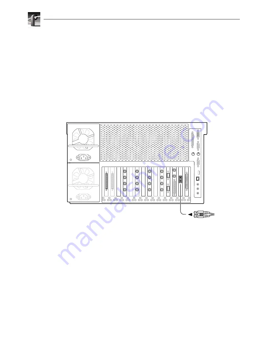
The Fibre Channel network interface uses a fiber optical connector located on the rear
panel as shown. Fiber optic cables are provided with your Profile XP system. If these
cables are not used, be sure to refer to Appendix B, “Connector Pin-outs”, for cabling
specifications.
Connect the fiber optic cable between the Fibre Channel switch and the Profile XP
network connectors as shown.
NOTE: Do not force the fiber optic plug into the Fibre Channel board connector as
you may damage the connector, the plug, or both. Make certain the fiber surface is
clean, free of dust or debris, before inserting the connector into the Fibre Channel
board connector.
You can connect your Profile XP systems together using a Fibre Channel switch.
0624-28
Profile XP Media Platform
From Fibre
Channel network
hub or switch.
Summary of Contents for PROFILE XP PVS Series
Page 14: ...Preface 14 Profile XP System Guide 23 July 2004 ...
Page 64: ...Chapter 2 Working with Configuration Manager 64 Profile XP System Guide 23 July 2004 ...
Page 130: ...Chapter 4 Adding or Removing Channels 130 Profile XP System Guide 23 July 2004 ...
Page 144: ...Chapter 4 Adding or Removing Channels 144 Profile XP System Guide 23 July 2004 ...
Page 232: ...Chapter 7 Modifying a Channel Timecode Settings 232 Profile XP System Guide 23 July 2004 ...
Page 238: ...Chapter 8 Modifying a Channel Ancillary Data 238 Profile XP System Guide 23 July 2004 ...
Page 246: ...Chapter 9 Managing Optional Licenses 246 Profile XP System Guide 23 July 2004 ...
Page 288: ...Chapter 11 Setting up a Simple Network 288 Profile XP System Guide 23 July 2004 ...
Page 310: ...Chapter 12 Solving Common Setup Problems 310 Profile XP System Guide 23 July 2004 ...
Page 344: ...Chapter C 344 Profile XP System Guide 23 July 2004 ...


