Zodiak Installation and Service Manual
105
Engineering Setups
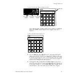
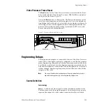
Video Processor Frame Reset
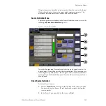
The
Reset
button for the Video Processor frame is located inside the front
door, on the left side of the Control Processor/DSK/Still Store module in
the top slot of the frame (
Next to the
Reset
button is a Boot switch. The Boot switch must be set to 0
(zero) for normal operation and software updates. This is the default set-
ting. Setting the Boot Switch to 1 (one) allows for loading boot software. In
this setting, in the event the application crashes during initialization, the
processor boots with only the operating system and an FTP server, and
does not launch the Zodiak application.
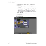
Figure 72. Frame Reset Button and Boot Switch
Engineering Setups
Zodiak inputs and outputs are connected to the rear of the Video Processor
frame. These video signals need to be configured to your facility’s require-
ments. Engineering setups define Zodiak system components and describe
how Zodiak is cabled into a facility. Engineering setups are intended to be
used and maintained by technical staff, and are designed to be set once and
seldom changed. Engineering setups may be loaded and saved to disk by
category, or all at once.
Note
The current Zodiak system configuration settings are automatically saved to
non-volatile storage when you exit an Engineering Setups menu.
Source Definition
Terminology
Source
– A collection of video signals and the information needed for the
Zodiak system to use these signals properly. At its simplest a source may
represent the output of a video camera connected directly to a Zodiak
ON
OFF
8125_00_18_r1
Reset Button
Boot Switch

