Zodiak Installation and Service Manual
111
Engineering Setups
Output Configuration
Program and Preview Outputs
Zodiak Program and Preview outputs are fed to dedicated BNCs on the
rear of the Video Processor frame. These output destinations cannot be
changed. The only configuration necessary is defining the clean feed
outputs for the downstream keys that will appear on either of the Program
outputs (PGM A and PGM B). This is done with the DSK menu, not part of
Eng Setups. Refer to
Other Configuration Settings on page 135
up the clean feed outputs.
Aux Bus Configuration
There are 9 Aux buses in the 2.5-M/E system and 13 in the 3-M/E system.
The Aux Bus video outputs are fed to BNC connectors on the rear of the
Video Processor frame. The physical Aux Bus output BNCs can be mapped
to any of the logical Aux Buses as desired. This is done with the Eng Setup
– Outputs menu.
Other Aux Bus attributes such as bus-to-panel delegation and Aux Pair
configuration are covered in menus outside of Eng Setups and will be
referred to in this section. Also refer to
Appendix C-External Interfaces
at the
end of this manual for a complete Aux Bus configuration example using
Aux pairs.
Mapping Aux Bus Physical Outputs
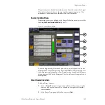
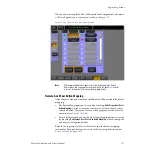
To map the Aux Bus physical outputs, touch the
Outputs
button at the
bottom of the
Eng Setup
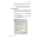
menu to display the Outputs menu (
). Depending on the type of equipment the Aux Bus is feeding,
some Aux Bus attributes are configurable, such as assigning Aux Pairs.
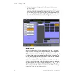
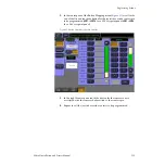
1.
Select a physical Aux Bus BNC number from the Physical Outputs pane
on the left of the screen.
2.
Select an Aux Bus number from the Logical Aux Bus pane on the right
to assign it to the physical output BNC connector.
3.
Touch the Logical Aux Bus Name data pad to bring up the
alphanumeric keypad. Enter the desired name of the Aux Bus and
touch
Enter
. The name of the Logical Aux Bus should appear in the
assigned physical output box.

