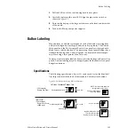
Zodiak Installation and Service Manual
139
Main Panel Maintenance
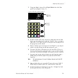
3.
Using your fingers, remove the six
Clip
and
Gain
knobs on the Main
panel Keyer subpanels (
).
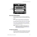
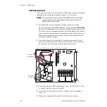
Figure 94. Main Panel Clip and Gain Knobs
4.
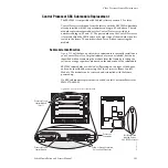
In order for the board to clear the tension spring that holds the Main
panel open, the spring must be released. Using a 7/16 in. screwdriver,
remove the 1/4 in. nut and washer on the right tension spring and lay
the spring down inside the tub.
5.
Remove the three screws securing the Control Panel Processor board’s
metal cover to the Main panel tub and remove the cover.
6.
Disconnect the ribbon cable attached to the Control Panel Processor
board by simultaneously pushing the cable connector’s left and right
ejector tabs outward and pulling the cable up and out of the connector.
7.
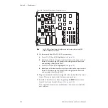
Disconnect the Joystick cable attached to the M/E Switch board by
pulling the Joystick cable connector down and out of the board
connector.
Note
The Joystick cable connector is clearly labeled on the bottom right of the M/E
Switch board.
8.
Support the board as you remove the 20 screws that secure the M/E
Switch board to the Main panel lid. Carefully remove the board.
9.
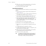
Install the replacement board by reversing
turn the power back on to the Main panel.
Int
DPM
Ext
DPM
Key
Invert
Show
Key
Matte
Fill
Freeze
Fill
Inhibit
Mask
Force
Mask
Video
Key
Freeze
Key
Key
Split
Key
Prior
Linear
Key
Lum
Key
Key
Chroma
Key
Preset
Pattern
Key
Key
2
Key
3
4
1
On
Keyers
Clip
Gain
M/E Keyers
Subpanel (3)
8125_00_19_r0
Knobs (2)
Per Panel

