Zodiak Installation and Service Manual
149
Video Processor Frame Maintenance
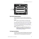
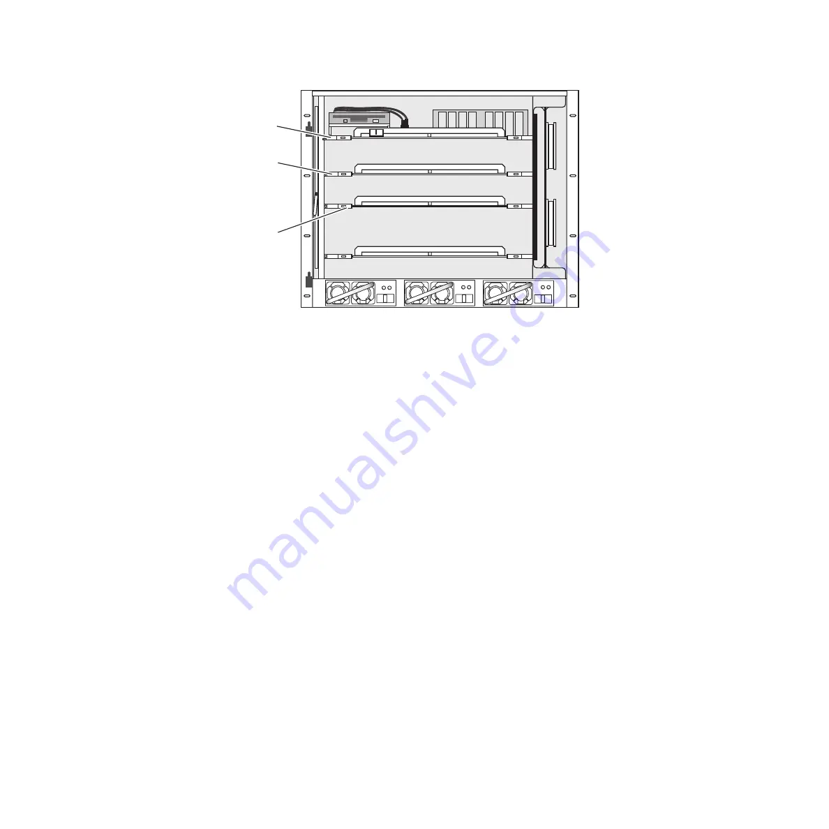
Figure 100. Zodiak Video Processor Frame
3.
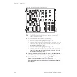
Confirm that the assembly number of the module is a 671-6347-00 or -
10 version, letter version E1 or earlier. Modules inked as -00 F1 or -10 F1
or later have already been modified at the factory.
The assembly number is silkscreened on the component side of the
circuit board as illustrated in
letter version is inked in the white box to the right of the assembly
number.
CAUTION
The ICs on this module may be quite hot when the module is first removed
from the frame. Let the module cool if necessary before proceeding.
4.
On the module from Slot 2 (2.5-M/E and 3-M/E systems):
a.
Locate ICs U12, U13, U45, and U46 highlighted in
b.
Install one of the four larger sized heat sinks on the top of each of
these ICs by removing the protective backing from the heat sink
and pressing it firmly onto the IC.
c.
Locate ICs U54, U55, U66, and U67 highlighted in
d.
Install one of the four smaller sized heat sinks on the top of each of
these ICs by removing the protective backing from the heat sink
and pressing it firmly onto the IC.
075069300_02
ON
OFF
M/E (M/E 1 & 2)
(Slot 2)
M/E (M/E 3)
(Slot 3)
Control Module
(Slot 1)


