Zodiak Installation and Service Manual
153
Video Processor Frame Maintenance
Note
The four spacers provided with the kit can be used with either the SBC1000
or the original submodule. You can discard the original spacers. Once you
have installed the new spacers you can skip steps 6 and 7 when re-installing
the submodule.
6.
Remove the four spacers.
7.
Install the four new spacers.
CAUTION
Careful alignment between the module and submodule connectors will
prevent bent pins. Check the alignment before pressing the submodule on to
the Control Processor.
8.
Check the connector pins on the solder side of the SBC1000 to be sure
they are not bent. Align the SBC1000 submodule and press it lightly on
to the Control Processor module. Do not seat the submodule yet.
9.
Check the alignment.
10.
Seat the SBC1000 submodule.
11.
Use the four #10 Torx screws to secure the corners of the submodule.
12.
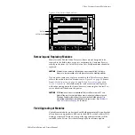
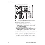
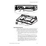
Connect the four cables, see
. Cable #3 must be connected
before cable #2, and cable #2 before cable #1.
Figure 104. Cable Connector Location for SBC1000 and Original Submodules
13.
Make a note of this change in your documentation for future reference.
14.
Return the Control Processor module to its original location in the
frame. You may plug the module back into the frame while it is
powered up. The module will reset and take the Zodiak system outputs
to black.
15.
Discard the original Frame Recovery floppy disk labeled with part
number 063-8067-01 that shipped with your system. This floppy disk
should no longer be used. Once you have installed the new SBC1000
you will need the Frame Recovery floppy disk included with FMN 075-
0689-00 for doing frame recovery.
0689_00_04_r0
SBC1000 Submodule
#4
#3
#1
#2
Original Submodule
#4
#3
#1
#2

