Zodiak Installation and Service Manual
167
Commonly Reported Problems
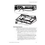
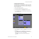
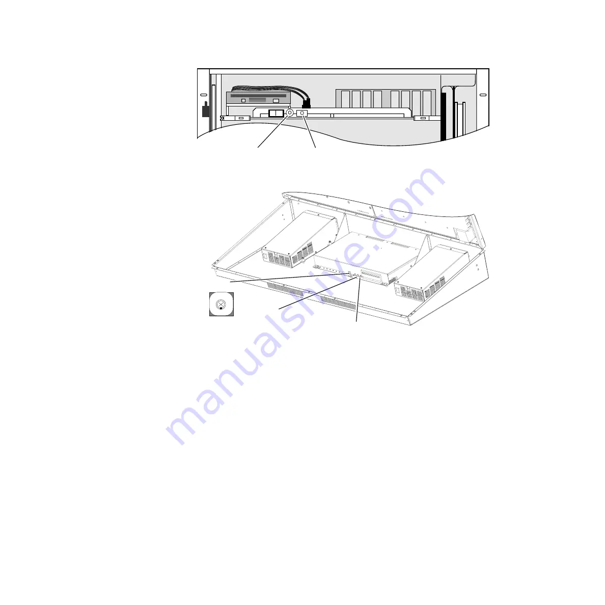
Figure 119. Control/SS/DSK Module Boot Switch and Reset Button
Figure 120. Main Panel Boot Switch and Reset Button
Check Network Connections
The Main panel and Video Processor frame communicate exclusively over
an Ethernet connection from the LAN connector on the rear of the Main
panel to the Control Panel LAN connector on the rear of the Video Pro-
cessor frame. Check that the connection is active by verifying the following:
•
Verify all cabling and connections are secure between devices. If using
a hub or switch in the network, verify power and communication at
these devices.
•
The green Link LED on the Main panel rear LAN connection is lit.
If the LINK LED is not lit, push the
Cross Over
button to the left of the
LAN connector. Wait about 10 seconds and if the LED does not light,
push the
Cross Over
button again to return it to the previous state.
•
The green MENU and PANEL LINK LEDs on the Control Pro-
cessor/DSK/Still Store module in slot 1 of the frame are lit and the
green TX and RX LEDs are blinking to indicate LAN activity (see
ON
OFF
8125_00_18_r1
Reset Button
Boot Switch
RT Panel Reset Button (on right)
(Main Panel Reset)
Menu Reset Button (middle)
(Windows 2000 Reset)
Boot Switch (0)
8125_00_12_r2
01
2
3
4 5 67
8
9


