188
Zodiak Installation and Service Manual
Section 5 — Troubleshooting and Diagnostics
b.
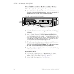
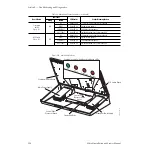
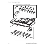
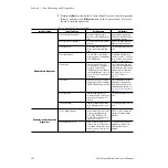
Check the status indicators on the Crosspoint Switch and M/E
Switch boards (
).
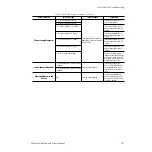
Refer to
for an overview of the status indica-
tors for the Control Processor, Crosspoint Switch and M/E Switch
boards and their meaning. The status indicators in the table are
listed as they appear on each board from the left side of the board
to the right.
3.
If the Main panel does not appear to be communicating properly (not
switching crosspoints or video, for example), check the communication
configuration at the Main panel to the other Zodiak devices.
For a quick check of system communication status with other devices,
check the version of Zodiak software running on the Main panel by
bringing up the Version screen on the Menu panel as described in the
steps below. If the Main panel is not communicating with the Menu
panel, a software version will not be reported.
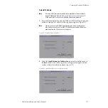
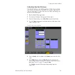
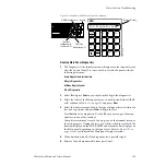
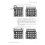
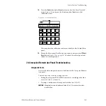
a.
Select the
Status/Diags
button from the Home menu on the Menu
panel.
b.
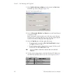
Touch the Versions data pad to bring up the software version
screen.
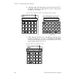
c.
The Version screen should report the Zodiak software version
running on each device communicating in the Zodiak system
(Video Processor frame, Main panel and Menu panel).
d.
Check that all reported software versions are identical. If one of the
software versions is different, reload the correct software version to
that device using the Software Installation Procedure described in
the current version of the Zodiak Release Notes.
4.
Verify that the Main panel to frame LAN connection is active by
checking the green LAN LINK LED on the rear of the Main panel. It
should be lit to indicate the LAN connection is active. If the LED is not
lit, push the
Cross Over
button next to the LAN connector. Wait about 10
seconds and see if the LED lights, if it does not, push the
Cross Over
button again to return it to the previous state. This button swaps the TX
and RX polarity required for communication with the frame.
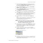
Check the Ethernet activity LEDs shown in
and
described in
. To do this you will need to remove
the metal cover over the Control Panel Processor board. Do this by
removing the three front screws holding it in place. Carefully lift off the
metal cover
Also refer to the detailed procedure,
Panel and Frame or System Lockup on page 166
, to troubleshoot commu-
nication problems.


