Zodiak Installation and Service Manual
189
Control Surface Troubleshooting
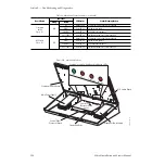
Table 18. Main Panel Status Indicators
Board Name
Indicator
LED Status
Status Meaning/Action
Group
Name
Control Panel Processor
Front Edge Indicators
)
A 12V
OK
Green LED on
+12 V power present from Main power supply.
FAIL
Red LED on
+12 V power not present from Main power supply.
A 5V
OK
Green LED on
+5 V power present from Main power supply.
FAIL
Red LED on
+5 V power not present from Main power supply.
B 12V
OK
Green LED on
+12 V power present from Redundant power supply.
FAIL
Red LED on
+12 V power not present from Redundant power supply.
B 5V
OK
Green LED on
+5 V power present from Redundant power supply.
FAIL
Red LED on
+5 V power not present from Redundant power supply.
Fuse
Indicators
XPT FUSE
Red LED on
+5 V to Crosspoint Switch board 5A 250V fuse is blown.
M/E FUSE
Red LED on
+5 V toM/E Switch board 5A 250V fuse is blown.
LOCAL FUSE
Red LED on
+5V 5A 250V fuse blown to Control Panel processor local power.
PNL 1 FUSE
Red LED on
+5 V to Satellite Panel 1 5A 250V fuse is blown.
PNL 2 FUSE
Red LED on
+5 V to Satellite Panel 2 5A 250V fuse is blown.
MENU FUSE
Red LED on
+12 V to Menu panel 8A 250V fuse is blown.
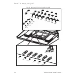
Control Panel Processor
(cover removed)
)
N/A
+3.3V
Green LED on
+3.3 V present from Control Processor board.
+2.7V
Green LED on
+2.7 V present from Control Processor board.
+1.8V
Green LED on
+1.8 V present from Control Processor board.
FAULT
Red LED on
Fault detected on Control Processor board.
RESET
Red LED on
System reset in process.
MSB – LSB
N/A
Not Used
HDD
N/A
Not Used
TxD
Green LED on
Data is being transferred from the CPU to the Panel LAN port.
RxD
Green LED on
Data is being received from the Panel LAN port to the CPU.
LINK
Green LED on
Ethernet controller recognizes Panel LAN connection.
COLDET
Red LED on
Collision fault detected.
10M
Green LED on
Ethernet transfer from Panel LAN is in 10BaseT mode.
100M
Green LED on
Ethernet transfer from Panel LAN is in 100BaseT mode.
TxD1
Green LED on
Data is being transferred from the CPU to Satellite Panel 1.
RxD1
Green LED on
Data is being received from Satellite Panel 1 to CPU.
TxD2
Green LED on
Data is being transferred from the CPU to Satellite Panel 2.
RxD2
Green LED on
Data is being received from Satellite Panel 2 to CPU.
Main Panel Backplane
)
N/A
LAN LINK
Green LED on
Ethernet controller recognizes Panel LAN frame connection.


