Zodiak Installation and Service Manual
209
Video Processor Frame Troubleshooting
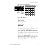
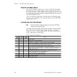
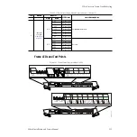
Figure 150. Video Processor Frame Power Supply Status Indicators
Fuses for the power supplies are not accessible. Replace a power supply
if an internal fuse is blown (either DC or AC LED is off).
Power to the Video Processor frame will shut off automatically if the
operating temperature becomes too high. An over temperature condi-
tion can be caused by fan failure or insufficient airflow allowances.
Once the system has cooled sufficiently it will restart. Once power is
restored, use the web browser described in
check fan and power supply status in the Video Processor frame.
For troubleshooting loss of DC power to the frame, also refer to the
detailed procedure in
No DC Power to Zodiak Component on page 184
Video Path Troubleshooting
The video path in the Zodiak Digital Processor frame is designed to
provide extremely flexible signal routing from input to output. Video paths
are configured through software under the Engineering Setup menu of the
Zodiak application during initial installation of the system. Although Engi-
neering Setup is not intended to be changed in the course of operation, ver-
ification of signal routing (input to output) is important to troubleshooting
loss of, or trouble with, video in the system.
Verify Input Video
If input video is missing, begin troubleshooting by verifying the Source
Definition configuration for each Crosspoint (see
Tally/GPI Relay Troubleshooting
There are 32 output tally relays on the Tally connector at J2. GPI outputs
feed 8 relays on the GPI connector at J1. All tally relays are fused with a
single 5A, 250V fuse (F1) located on the Control Processor/DSK/Still Store
module in slot 1 of the frame.
Configuration of tallies and GPIs is done in the Eng Setups menus in the
Zodiak Menu application. Refer to
Engineering Setups on page 105
figuration details.
8096_00_22_r1
P/S Slot 1
P/S Slot 2
P/S Slot 3
V DC AC
V DC AC
V DC AC

