Zodiak Installation and Service Manual
217
Video Processor Frame Modules
Video Processor Frame Power Distribution
The + 48 V DC power from the power supplies enters a Power Transfer
module before going to the switcher backplane where it is distributed to all
frame modules. Each module is fused to provide protection from over-
current damage. Each frame module has its own DC-to-DC voltage con-
vertor that receives the + 48 V DC as input, and outputs the necessary DC
voltages for use by the particular module.
Video Processor Frame Modules
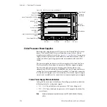
Up to four hot-pluggable modules are installed in the front of the Video
Processor frame (
). The modules plug into a backplane
where they receive DC power and the signals from each module are distrib-
uted throughout the system. All frame modules have metal guide pins to
prevent errors when inserting modules. The modules are listed in
and shown in
In some cases, “like” modules (for example, The M/E modules) have the
same guide key position. “Like”modules can be placed in the wrong slot
and no damage occurs. However, the module may not operate correctly
.
Video Processor Frame Modules
A brief overview of each of the Video Processor frame modules is given
here. Refer also to the simplified block diagram shown in
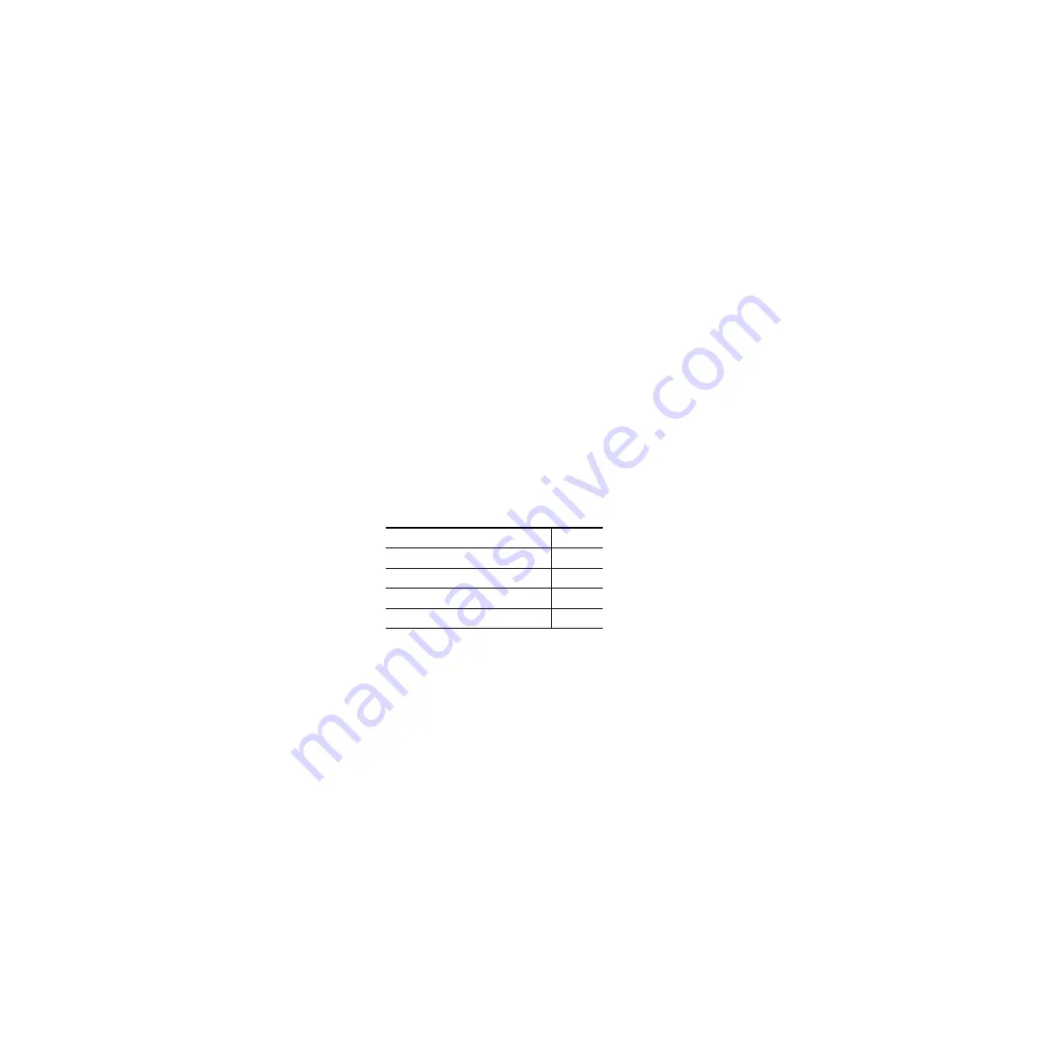
Table 24. Frame Module Locations
Module Name
Slot #
Control Processor/DSK/Still Store
1
M/E Module (M/E 1 & M/E 2)
2
M/E Module (M/E 3)
3
Input/Crosspoint/Sync Generator
4

