Zodiak Installation and Service Manual
227
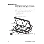
Zodiak Main Panel
Power (+5 V) and control panel data to and from the host Control Panel
Processor is passed via a single 34-pin ribbon cable. The Control Panel Pro-
cessor writes and reads data from the parallel slave port of a PIC microcon-
troller on the Crosspoint Switch board. The PIC is responsible for reading
the switches and lighting their tally LEDs.
Power and status indicator LEDs are provided on the board (
M/E Switch Board
The M/E Switch board is mounted inside the Main panel lid on the right
(
). It contains circuitry for the following control
panel functions:
•
Pushbuttons and lamps for re-entry crosspoints and Aux Bus delega-
tion,
•
M/E Transition subpanel pushbutton and lamp controls and lever
arms,
•
Joystick control and transform pushbuttons and lamps,
•
Shaft encoders for Clip and Gain,
•
Effects Memory pushbuttons and alphanumeric displays,
•
M/E Keyer subpanel LEDs, pushbutton and lamp controls,
•
Fade to Black pushbutton and alphanumeric display, and
•
DSK subpanel and LEDs.
Power (+5 V) and control panel data to and from the host Control Panel
Processor is passed via a single 34-pin ribbon cable. The host Control Panel
Processor writes and reads data from three parallel slave ports of PIC
microcontrollers for M/E 1, M/E 2 and M/E 3 (PGM/PST). Any analog
information from panel circuitry is first processed in A–D converters before
passing to the microcontrollers.
Power and status indicator LEDs are provided on the board (

