230
Zodiak Installation and Service Manual
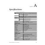
Appendix A — Specifications
Output Impedance
75 ohm
Ancillary Data
Included in each M/E and DSK Program output
DC Offset on Output
< 50 mV across 75 ohm termination
Number of Bits
10
Number of Outputs
2 BNC connectors per channel
Analog Reference Input
Black
Composite Color Black (NTSC or PAL), 525 (60 Hz) or 625 (50 Hz)
Connectors
Two 75 ohm BNC
Return Loss
> 40 dB to 5 MHz
Impedance
75 ohm loop through
System Timing
Switcher Output Delay
49 microseconds
1
1
All measurable parameters meet the specifications defined in this appendix.
2
The equipment runs safely without damage, but inconsistencies with the specifications defined in this appendix may
occur.
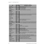
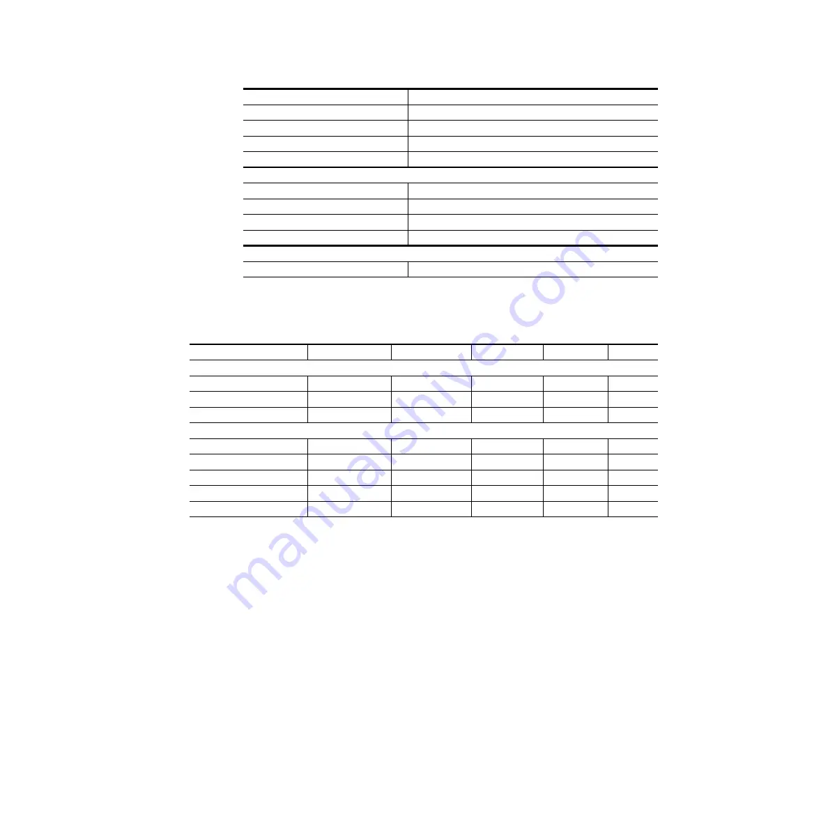
Table 26. Zodiak Mechanical Specifications
Component
Depth
Width
Height
Weight
1
Rack Units
Standard
Video Processor Frame
22.13 in. / 562 mm
2
19.0 in. / 483 mm
3
12.25 in. / 311 mm 79lb / 36 kg
7
Main Panel
18.75 in. / 476 mm
4,
5
40.97 in. / 1041 mm
5.82 in. / 148 mm
6
86 lb / 39 kg
N/A
Menu Panel
7
4.30 in. / 109 mm
14.75 in. / 375 mm
8
10.1 in. / 257 mm
17 lb / 7.7 kg
N/A
Options
KAL-24AUX1 Remote Aux Panel
2.0 in. / 51 mm
19.0 in. / 482 mm
1.75 in. / 45 mm
2.25 lb / 1.02 kg
1
KAL-24AUX2 Remote Aux Panel
2.5 in. / 64 mm
19.0 in. / 482 mm
3.5 in. / 89 mm
4.5 lb / 2.04 kg
2
KAL-24AUX3 Remote Aux Panel
2.5 in. / 64 mm
19.0 in. / 482 mm
5.25 in. / 133 mm 6.75 lb / 3.06 kg
3
KAL-32AUX1 Remote Aux Panel
5.25 in. / 133 mm
19.0 in. / 482 mm
1.75 in. / 44 mm
2.06 lb / 0.93 kg
1
KAL-32AUX2 Remote Aux Panel
4.25 in. / 108 mm
19.0 in. / 482 mm
3.5 in. / 89 mm
2.25 lb / 1.02 kg
2
1
All weights approximate.
2
Allow an extra 4.0 in. (102 mm) for cable.
3
Allow an extra 4.0 in. (102 mm) on the left and right of the frame for air flow.
4
Allow a minimum of 6.0 in. (152 mm) of clear space at the rear of the Main panel below the mounting surface for proper cable clearance
and air flow. Allow an extra 8.0 in. (203 mm) to 10.0 in. (254 mm) of mounting surface behind the Main panel for peripheral components.
5
Indicated measurement is for the lid. Refer to installation detail for tub measurements.
6
Add 0.25 in. (6 mm) for rubber feet on bottom of tub if required. Indicated measurement is from bottom surface of tub to top surface of
lid.
7
Not including mounting bracket.
8
Allow an extra 5.8 in. (147 mm) clearance for the CD drawer and fan exhaust.
Table 25. Zodiak System Specifications - (continued)

