268
Zodiak Installation and Service Manual
Appendix C — External Interfaces
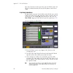
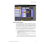
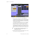
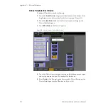
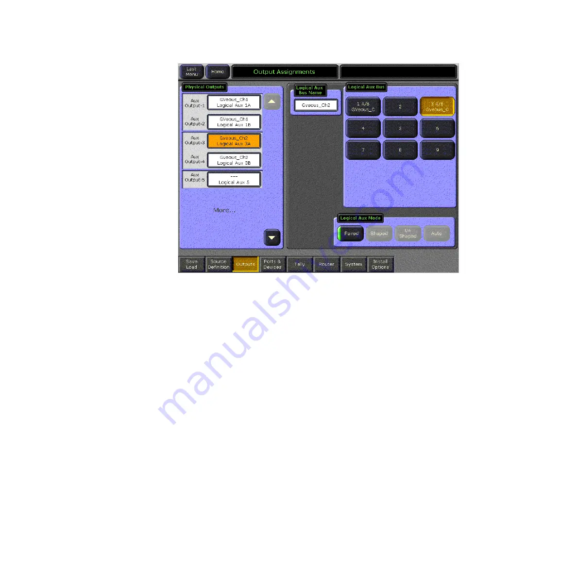
Figure 179. Ports & Devices – Assign Aux Buses – GVeous
3.
Define Aux bus pairs if required by touching the
Paired
button.
You may also pair two Aux buses to send a Video/Video or Key pair to
the DPM as shown in the example in
buses allows you to output the selected video source on one Aux bus
and the key (or video) associated with that source (in Source Definition)
on the other Aux bus in the pair.
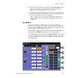
For example, if you select Aux Output 1 above and touch the
Paired
button in the Logical Aux Mode data pad, Aux Buses 1 and 2 will be
paired as shown in
. A name can be given to the pair.
The video source selected on Aux Bus 1 will be sent to the Aux Bus 1
output while the key associated with the source will be sent out Aux
Bus 2 simultaneously. Only Aux pairs 1 and 2, 3 and 4. 6 and 7, 8 and 9,
10 and 11 and 12 and 13 may be paired. Aux Bus 5 cannot be part of a
pair.
Note
In future releases, Aux Bus pairs 6 and 7, 8 and 9, 10 and 11 (3-M/E), and 12
and 13 (3-M/E) will have effects send capability and will allow
shaping/unshaping of the signal pair.
4.
Name each Aux bus or Aux bus pair by touching the Logical Aux Bus
Name data pad and entering an appropriate name.

