Zodiak Installation and Service Manual
279
Peripheral Bus II
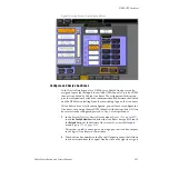
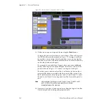
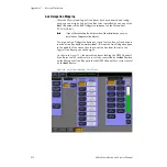
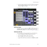
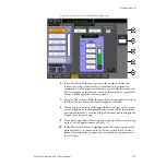
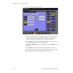
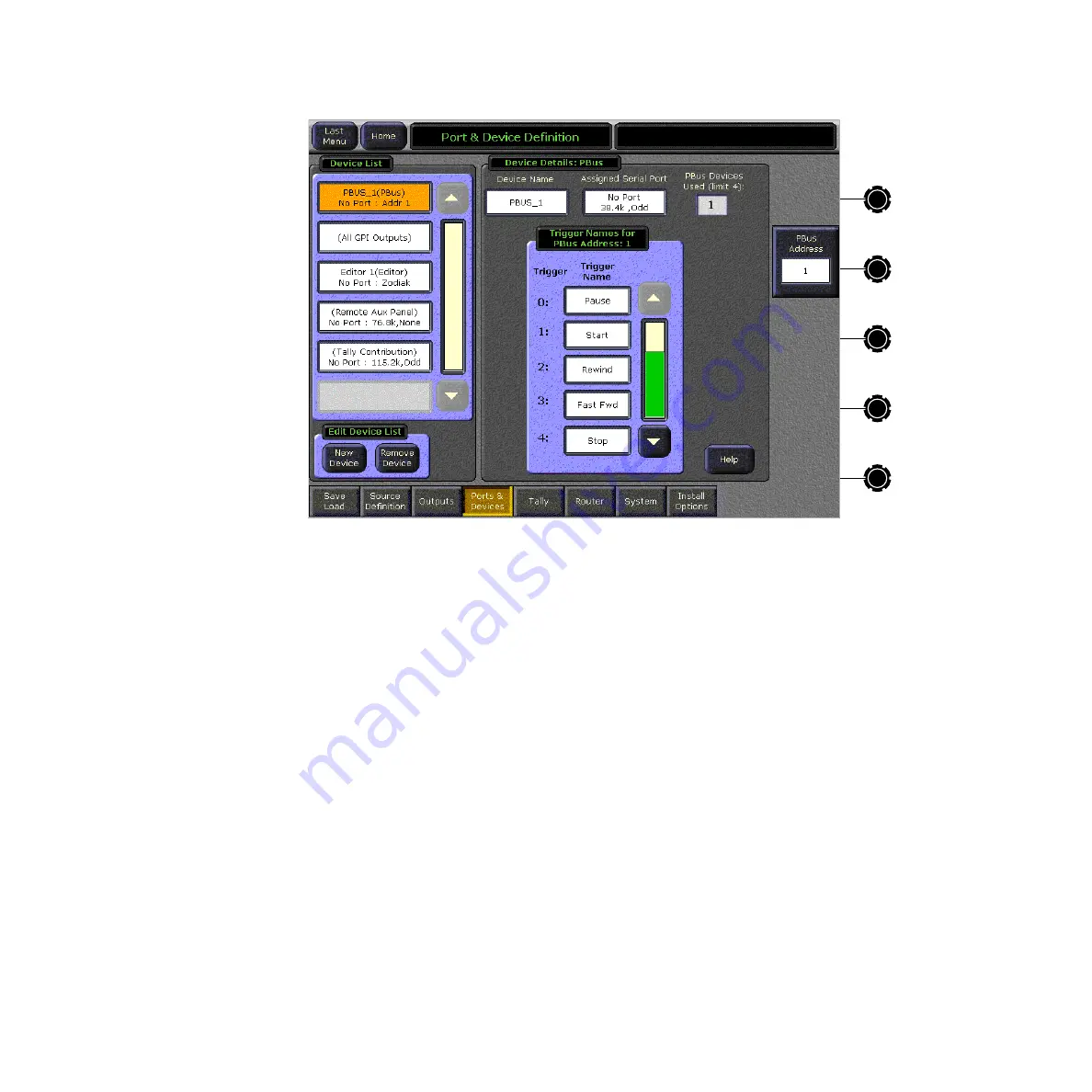
Figure 186. Ports & Devices – Peripheral Bus II Configuration
6.
In the Ctrl Delay Fields data pad, enter the number of fields that
indicate how long it takes for the external device to respond to a
command. Use the keypad or soft knob to enter a value between 0 – 60.
This external device information is used by the switcher to synchronize
Master E-MEM operations more accurately.
7.
Enter the PBus address (
0–23
) to match that of the peripheral device in
the PBus Address data pad with the keypad or soft knob.
8.
Enter a Trigger Name for each Trigger (
0–15
) according to what action
will be triggered on the peripheral device (as defined by the external
device manufacturer). Touch the Trigger Name data pad to bring up the
keypad for entering a name.
9.
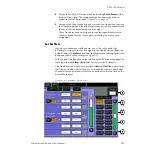
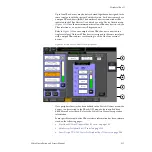
Touch the Assigned Serial Port data pad at the top of the screen to bring
up the Port Configuration menu (
10.
In the Physical Serial Port Assignment pane, touch the serial port the
peripheral device is connected to on the rear of the Video Processor
frame. The name of the peripheral device should now appear next to
the serial port.

