28
Zodiak Installation and Service Manual
Section 1 — System Overview
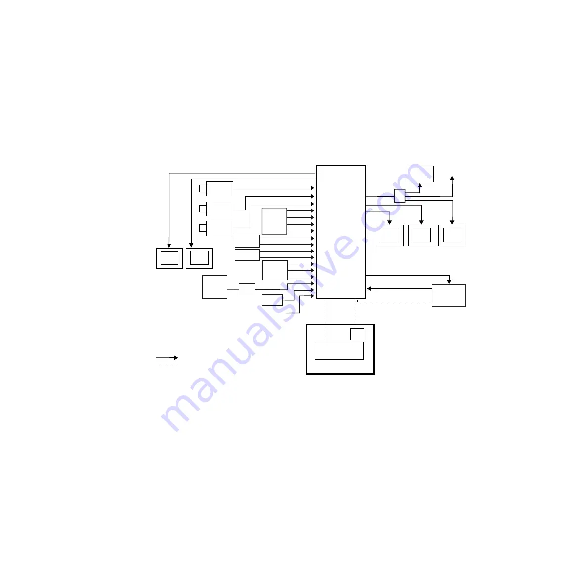
Zodiak Facility Example
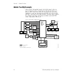
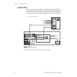
A basic facility configuration example of a Zodiak system is shown in
. Numerous types of sources can be fed to the Video Processor
frame. Each M/E, Keyer and Utility bus has internal video processing
capability to correct color (including optional RGB color correction) and
add effects. In addition to the optional internal Transform Engine capabili-
ties available on each keyer, this facility also utilizes an external DPM
system configured for Effects Send.
Figure 6. Basic Facility Configuration Example
Program
Monitor
Preview
Monitor
Other
Monitors
Program Out
Master Control/
Transmitter
Video/Key (Effects Send)
Cam 1
Cam 2
Cam 3
Video/Key (Effects Return)
Synchronous Serial (CPL)
Reference Black
Aux Bus Outputs
8096_00_18_r4
Zodiak Main Control Surface
Zodiak Control
Monitor
Monitor
Zodiak
Video
Processor
Frame
DPM
1
VTR
1
CPL Compatible DPMs: Krystal, GVeous/Dveous
Video or Key Signal
Control Line
Menu
Panel
Main Panel
Menu LAN
Panel LAN
Profile
VDR
Character
Generator
Router
TSG
Paint
System
Analog
VTR
Video/Key
Video/Key
8900
Series
DA

