286
Zodiak Installation and Service Manual
Appendix C — External Interfaces
Editor Installation and Configuration
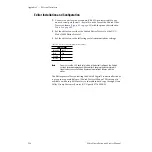
1.
Connect the editor with a standard RS-422 9-pin serial cable to any
unused serial port (Serial 1 – Serial 4) on the rear of the Zodiak Video
Processor frame (
) with the pinout described in
2.
Set the editor to use either the Zodiak Editor Protocol or the GVG
Model 4000 Editor Protocol.
3.
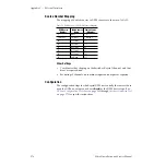
Set the editor to use the following serial communications settings:
Note
You must use the 38.4 baud rate (which is the default setting on the Zodiak
system) for proper operation with an editor. Changing the baud rate to dif-
ferent values can cause Zodiak frame communications failures with the
editor.
The Editor protocol for controlling the Zodiak Digital Production Switcher
is given in a separate Kalypso/Zodiak Protocol Manual. This manual is
available on-line in .pdf format or is orderable in hard copy through Grass
Valley Group Customer Service (GVG part # 071-8063-XX).
Table 41. Editor Serial Communication Settings
Serial Settings
Baud Rate
38400
Parity
Odd
Stop Bits
1
Data Bits
8


