58
Zodiak Installation and Service Manual
Section 2 — Installation
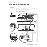
Cabling and Pinouts
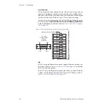
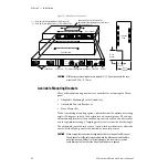
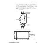
illustrates the cabling between the Menu panel and
other system components. The cable for connection between Com 3 on the
Menu panel and Com 1 on the Main panel is provided with the system.
This cable activates the Menu panel reset button located inside the Main
panel.
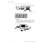
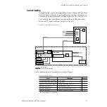
provides pinouts for the Menu panel console ports.
Table 6. Menu Panel Console Ports
Console Ports
RS-232
Pin
Menu Proc.
COM 3
Menu Proc.
COM 4
1
DSD
DSD
2
RXD
RXD
3
TXD
TXD
4
DTR
DTR
5
Chassis GND
Chassis GND
6
DSR
DSR
7
RTS
RTS
8
CTS
CTS
9
Menu Reset
1
1
Open circuit or Mark (-5 to -15 volts) is run. Space (+5 to +15 volts) is reset.
RI (Ring Indicator)
Pin 1
Pin 9
Pin 6
D-9 Male
Pin 5

