68
Zodiak Installation and Service Manual
Section 2 — Installation
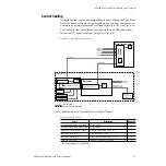
Cabling and Pinouts
illustrates the cabling between the Video Processor
frame and other system components. Pinouts for the various Video Pro-
cessor frame ports and connectors are given in
(Tally Port). Configura-
tion of these ports is done using the Zodiak Menu application (refer to
Table 8. Video Processor Frame GPI Inputs and Outputs
GPI
Pin
Function
Pin
Function
1
Chassis GND
20
IN 1B
2
IN 1A
21
IN 2B
3
IN 2A
22
IN 3B
4
IN 3A
23
IN 4B
5
IN 4A
24
Chassis GND
6
IN 5B
25
IN 5A
7
IN 6B
26
IN 6A
8
IN 7B
27
IN 7A
9
IN 8B
28
IN 8A
10
Chassis GND
29
OUT 1B
11
OUT 1A
30
OUT 2B
12
OUT 2A
31
OUT 3B
13
OUT 3A
32
OUT 4B
14
OUT 4A
33
Chassis GND
15
OUT 5B
34
OUT 5A
16
OUT 6B
35
OUT 6A
17
OUT 7B
36
OUT 7A
18
OUT 8B
37
OUT 8A
19
Chassis GND
Notes:
Inputs are opto-isolated.
A and B are polarity independent.
Apply from 5 to 24 volts between A and B Inputs to turn on.
Outputs are normally open relay closures between A and B.
Pin 1
Pin 19
Pin 20
Pin 37
D-37 Female


