70
Zodiak Installation and Service Manual
Section 2 — Installation
Zodiak Control Surface Cabling and Control
Cabling
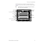
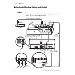
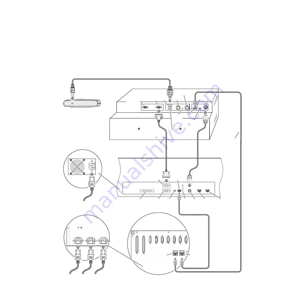
The cabling of a standard Zodiak Control Surface is illustrated in
Refer to
for a list of supplied cables.
Figure 46. Zodiak Control Surface Cabling
115V/230V
(2 places)
Main Panel
AC In
COM 4
(Spare)
8125_03_14_r3
Menu Panel Bottom View
Main Panel Rear View
Zip Drive
Frame
Rear View
Frame
AC In
GPI
Link
LED
SAT
Panel 1
(Unused)
SAT
Panel 2
(Unused)
COM 2 Cross Over
Button
COM 1
COM 3 USB
External CD-ROM
Drive (Option)
Mouse
DC In
Menu
Power
USB with
DC Power
115V/230V
PS 1
PS 2
PS 3
Keyboard
Reset
Button
LAN
LAN
Cross Over
Button
GPI
Tally
Diag
Serial 1
Power Supply 1
AC
Power Supply 2
AC
Power Supply 3
AC
Serial 2 Serial 3 Serial 4
CPL1
CPL 2
Link
LED
Use Hub If
Exceeding
328 ft (100 m)
Menu
Display
Control
Panel
J10
J11
Cable must be connected to Com 3 on the
Menu panel and Com 1 on the Main Panel.

