76
Zodiak Installation and Service Manual
Section 2 — Installation
Video
Different video and control wiring configurations may be used to meet
individual facility requirements. All Zodiak system video inputs and AUX
outputs are configurable. For cabling configuration flexibility, each input
can be mapped to any Zodiak panel source select button, and any Zodiak
system video signal can be mapped to any AUX output connectors.
Program and Preview bus outputs for each M/E have dedicated output
connectors as well.
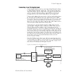
Refer to
for an example of a basic Zodiak system con-
figuration.
Inputs
Physical inputs are the actual BNC connectors that feed a signal into
Zodiak. These non-looping inputs on the back of the Video Processor frame
are numbered 1 through 64. Each receives a 270 MHz serial digital video
signal. All video inputs are software configurable, and each input can be
mapped to any Zodiak panel source select button. For correct operation of
the autotimer circuits, inputs should arrive at the switcher ± 10 microsec-
onds of the reference input.
Outputs
The Zodiak frame provides dedicated program and preview video output
connectors for each M/E. Each 270 MHz serial output signal is available on
two BNC connectors. Any Zodiak video source can be routed to any Aux
bus output (1 through 13).
Reference Input
The looping reference input accepts analog 525 or 625 composite video.
Burst is not required, but typically facility reference color black is used. The
timing of all switcher inputs and outputs are referenced to this signal.
Zodiak automatically switches between 525 and 625 mode to match the
standard of the reference input signal.


