Zodiak Installation and Service Manual
107
Engineering Setups
Logical names, Logical nicknames, and Logical IDs are intended to identify
the use of a source for a particular show. For example, VTRs may be given
Blue, Red, and Gold Logical names. DDR channels might be named A, B,
and C. Cameras might be identified by the camera number and each oper-
ator's name (which may change from program to program). To support this
added level of variability, both Logical names and Logical nicknames can
be used to label sources differently for varying conditions.
The Zodiak system also provides a way to map Engineering source IDs to
Logical source IDs, using the Source Patch feature. By default this mapping
is one-to-one, but this feature can be used to quickly set up production ele-
ments for use in a different facility. For example, a show’s effects, DDR
clips, and taped material may have been built in one production truck with
one set of devices, but the next show is scheduled for a different truck. Pre-
viously, to use effects in the other truck the Technical Director (TD) would
need to edit the engineering source definitions in the new truck so they
exactly matched the old truck. In some cases six settings would have to be
changed, and tally outputs would also need to be repatched. With the
Zodiak 4.0 release, by remapping the Engineering sources of the devices in
the new truck to the Logical sources used to build the effects, all the effects
can be used without having to edit them. Source Patch can also be used to
quickly swap out a defective device during a show without having to
reconfigure the Engineering sources. In this case Logical names seen by the
production personnel would be identical for that content, even though the
actual device playing the material changed.
The source definition tells the system which physical inputs or internal
signals to use when a particular source is selected. The source definition,
denoted by a source ID number, specifies how to process a signal, and what
external devices and key signals, if any, are associated with that source.
Source definition defines what signals comprise each source. The default
Source Select button definitions are set up at the factory such that Input 1 =
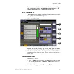
Source 1, Input 2 = Source 2, etc. The Eng Setup – Sources menu is used to
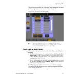
change source definitions. Touch the
Eng Setups
button on the Menu panel,
then touch the
Sources
button at the bottom of the screen to display the
).
There are a total of 92 assignable sources, including internally generated
signals. The sources can use, as inputs, 64 physical BNC connectors on the
rear of the Video Processor frame, or internally generated signals and re-
entries, such as Background mattes, black, internal Still Stores, and the
Program and Preview outputs from each M/E level. The internal signals
are assigned in the Button Mapping menu (see
).
Source Types
Each source must also be defined as a Source type. Source types include
Direct
,
Device
,
Router
,
DPM Physical
, or
DPM Logical
. Direct sources are defined as
sources internally generated in the switcher or fed directly to a BNC on the


