112
Zodiak Installation and Service Manual
Section 3 — Configuration
4.
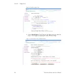
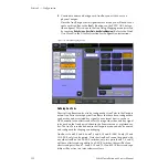
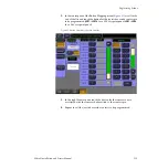
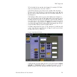
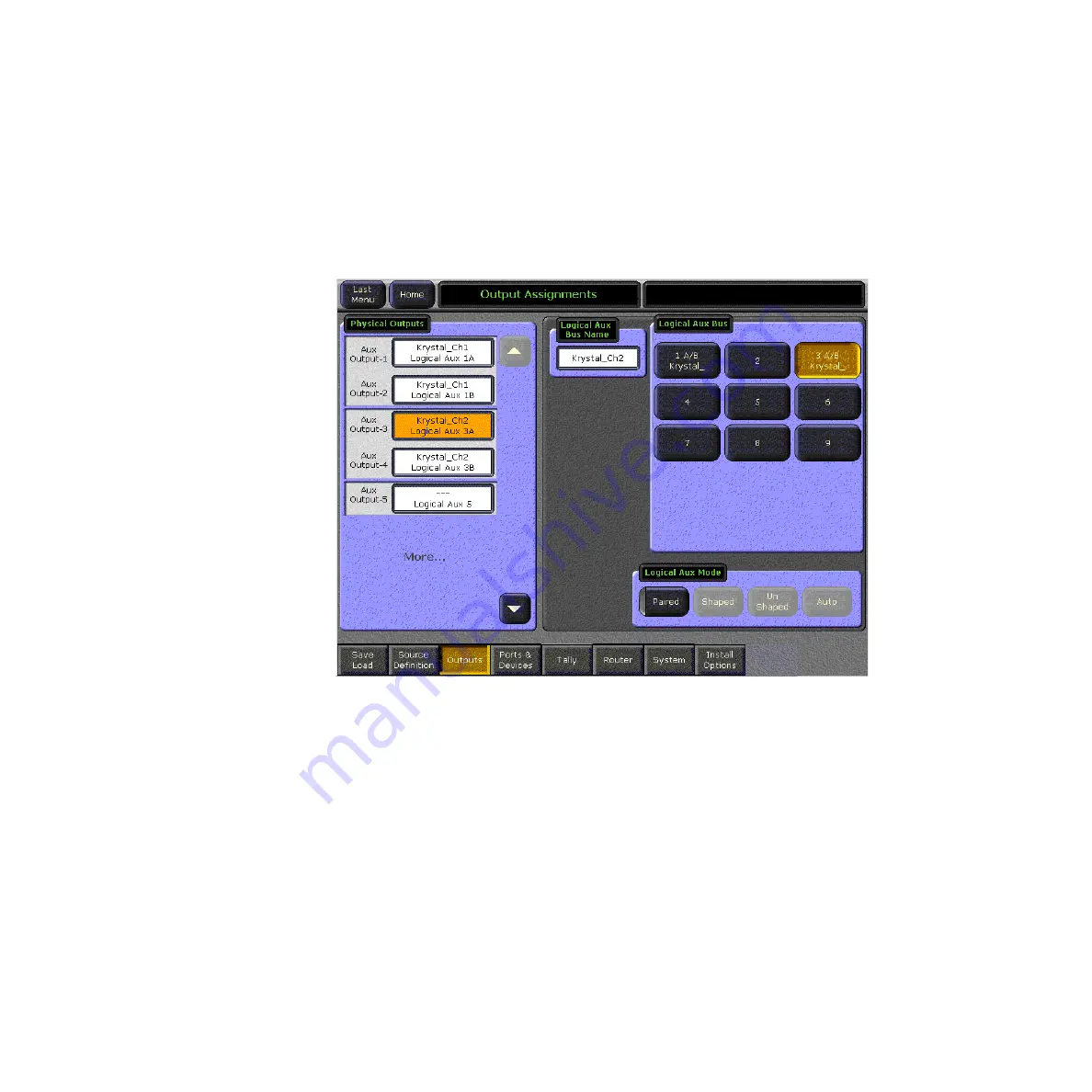
Continue to name and assign each Aux Bus you wish to use to a
physical output.
Once the Aux Bus physical assignments are made, you will need to del-
egate each Aux Bus to the
Aux 1 – 9
buttons on the PVW/AUX delega-
tion subpanel. This is done in the Aux Deleg Mapping menu (accessed
by touching
Daily Setups
,
User Prefs
,
Aux Deleg Mapping
). Refer to the Zodiak
User Manual in the User Prefs section for configuration instructions.
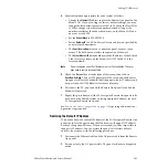
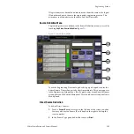
Figure 74. Output Mapping Menu
Defining Aux Pairs
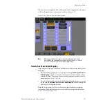
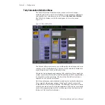
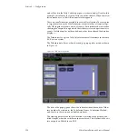
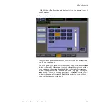
Physical Aux Buses can be also be configured as Aux Pairs in the Outputs
menu. Aux Pairs are two physical Aux Buses that have been configured to
send a video and associated key signal to an external device, such as a
DPM, usually for an effects send effect. Pairing of the video and key signal
to be used on the Aux bus is defined in the Sources menu as explained ear-
lier. The Aux Pair can be defined in the Outputs menu and also be named
and configured for shaping or unshaping.
Aux Buses 1 and 2, 3 and 4, 6 and 7, 8 and 9, 10 and 11 (3-M/E only), 12 and
13 (3-M/E only) can be paired. Note that Aux Bus 5 cannot be paired with
any other Aux Bus. In a 2.5-M/E switcher, only two pairs (6 and 7, 8 and 9)
will have effects send capability. In a 3-M/E switcher, there will be four
effects send pairs (6 and 7, 8 and 9, 10 and 11, 12 and 13). Effects send capa-
bility will be active in a later software release.


