196
Zodiak Installation and Service Manual
Section 5 — Troubleshooting and Diagnostics
7.
Return the
Boot
switch on the Control Panel Processor board to position
0
(zero) and press the
RT Reset
button on the Control Panel Processor
board to resume operation.
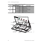
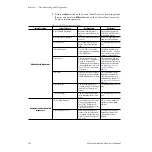
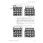
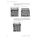
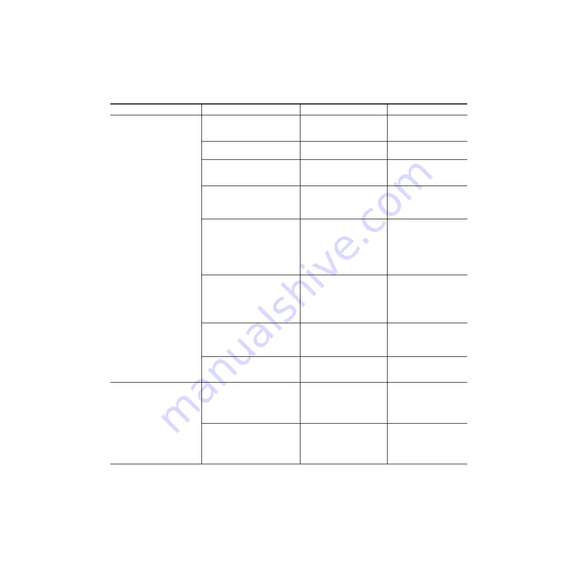
Table 21. Main Panel Diagnostics Menus
Select Test Area
Select Test Type
Test Procedure
Test Result
B Button Board Diagnostics
A Test All Boards Sequentially
Buttons will light in groups of
eight. Press each lit button to turn
it off.
After all buttons are pressed,
DONE PASS or DONE FAIL will
be reported to terminal.
B Test Panel Buttons Randomly
Push each switch button individu-
ally to test.
Button should light when held
down, go out when released.
C Test Light Levels
Observe light intensity levels of
buttons, text displays and light
pipes.
Test will loop through until user
exits.
E Test Shaft Encoders
Turn each M/E’s Clip and Gain
knobs and observe corresponding
M/E E-MEM display.
Clip NN and Gain NN values
should vary from 0 – 99 (clock-
wise = positive values, counter-
clockwise = negative values)
J Test Joystick
Move the joystick to the up (X
axis), down (Y axis), and rotate (Z
axis) limits. View each M/E
E-MEM display. Axis will appear in
Transition Rate display (
ton for beep.
The calibrated low, high and
current value will be displayed.
Calibration data is either factory
default or latest calibrated val-
ues. Refer to
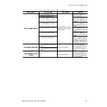
L Test Levers
Move each lever arm to its upper
and lower limit. View correspond-
ing M/E E-MEM display for values.
The calibrated values will be
displayed. Calibration data is
either factory default or latest
calibrated values. Refer to
P Test Light Pipes
View each light pipe (Key On,
Lever Arm direction, Effects Send,
and Uncal) until it reaches full
intensity.
Test will loop through until user
exits.
T Test Text Displays
View each alphanumeric display
on the Main panel as text scrolls
across.
Test will loop through until user
exits.
I Indicators and Rotary Switch
Diagnostics
I Test On-Board Indicators
Remove metal cover from Control
Processor board and observe
FAULT, 10M, 100M and LSB –
MSB (8) LEDs blinking. Refer to
.
LEDs will cycle through blink
sequence to indicate proper
operation.
R Test Boot Rotary Switch
Rotate the Boot rotary switch on
the front of the Control Panel Pro-
cessor board through all positions
within 10 seconds. See
An error message will be dis-
played on the terminal if all
switch positions are not
detected.


