274
Zodiak Installation and Service Manual
Appendix C — External Interfaces
Krystal CPL Interface
The following CPL interface functions are supported in a Krystal device:
•
Krystal effect recall via E-MEM,
•
CPL effect run control, and
•
Krystal control of Zodiak Aux buses for source selection (keyframable).
Krystal Combiner Requirements
If the Zodiak system feeds a background video input to an optional Krystal
Combiner, a serial digital delay device is needed to time the background
video to the video passing through the Krystal DPM.
Control Interface Cabling
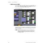
For CPL control, connect an RS-422 cable from the
CPL 1/J8
or
CPL 2/J9
port
on the rear of the Zodiak Video Processor frame to the Krystal Effect
Manager I/O module
Switcher J4
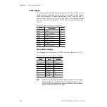
port. Zodiak cable pinouts are given in
On multiple-user systems with multiple switchers, each switcher is gener-
ally dedicated to a separate Krystal Effect Manager. Otherwise, arrange-
ments must be made for signal control routing external to the Krystal and
switcher control systems.
Video Cabling
Currently, no Effects Send capability is enabled in the Zodiak software. In
software version 1.2.0, Zodiak Aux bus outputs can be connected to Krystal
inputs and controlled by the Krystal (see
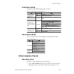
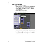
Configure and Assign Aux Buses on
). The Krystal outputs are then connected to Zodiak inputs and
defined as DPM Physical sources.
Krystal DPM Inputs
Each Krystal Video Processor frame has two pairs of serial digital video
inputs (Video A, Key A, Video B, Key/Mask B). How you connect these
inputs to the Zodiak system depends on whether you use the External
Source Selection, Internal Switching, or A/B Input Routing features avail-
able on the Krystal DPM. These configurations provide different opera-
tional capabilities. See the Krystal 4300 Installation and Service Manual for
more information.
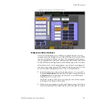
Krystal inputs should be fed with Zodiak Aux bus outputs. Aux bus con-
figuration must be performed then Aux bus assignments are made in

