Zodiak Installation and Service Manual
275
DPM CPL Interface
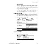
Krystal DPM Outputs
Each Krystal Video Processor frame has three video outputs: Key/Depth,
Preview, and Program. How you connect these outputs to the Zodiak
system depends on the Krystal options available (Combiners, Graphics,
etc.) and your specific facility configuration. See the Krystal 4300 Installation
and Service Manual for more information.
In software release 1.2.0, connect the Krystal outputs to Zodiak input
source BNCs on the rear of the Video Processor frame and define them as
DPM Physical sources (refer to
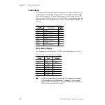
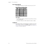
Source Number Mapping on page 276
).
Zodiak Required Settings
The Zodiak system Inputs, Outputs, and External Interfaces must be prop-
erly configured for successful integrated DPM operation. Some of the spe-
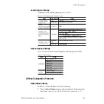
cific settings involved are listed in
Krystal Required Settings
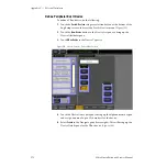
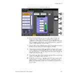
The system settings required for Krystal are summarized in
Table 33. Zodiak Configuration Settings for Krystal
Menu
Pane/Category
Setting
Eng Setups - Outputs
(for each Zodiak output
going to Krystal)
Mode
Aux Pair
(if desired, not a requirement)
Aux Bus Pairs
Select Aux bus for each output.
Aux Bus
(for B Channel of any
paired Aux Buses used by
Krystal)
B Channel is:
Key
Eng Setups -Ports &
Devices (define the device,
then use for each source
above)
Define Device
Device Name: Enter descriptive name of Krystal system.
Assigned Serial Port:
CPL 1
or
CPL 2
Device Type:
DPM
Protocol:
Krystal
Aux Bus Feeding Channel: Identify Aux buses used by each
Krystal channel.
Eng Setups - Sources
(for each Krystal source)
Engineering Name
Enter descriptive name of source.
Source Type
DPM Physical
Table 34. Krystal Configuration Settings for Zodiak
Menu
Setting
External Control Prefs
Switcher Port: Enable
Src Select Device
External Switcher Device Installed
Src Select Config
[V, K] or [V, K, M] inputs assigned, depending on cabling
Port Config
Switcher CPL protocol


