170
Detail program description - Wing mixers
AiI-tr.
(aileron trim)
(suppressed by "2AIL 1FL")
Fl.pos
Diff.
Ail-tr
Al
Normal
AILE
+100%
FL2
FLAP
0%
0%
0%
+100%
0%
+100%
0%
+100%
0%
0%
0%
0%
+100%
0%
0%
0%
FL
+100%
+100%
0%
0%
0%
0%
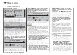
In this line, you specify the percentage rate with
which aileron trim is to affect "AILE", "FLAP" and – if
present – "FLAP2".
The available range of values is -150 % to +150 %,
relative to the adjustment range of the trim wheel.
A simultaneous tap on the
cd
or
ef
keys of the right
touch pad (
CLEAR
) will reset the given active (inverse
video) fi eld to its default value shown in the fi gure.
Diff.
(Differential for aileron function)
(With "2AIL 1FL", at one level higher in the
»
Wing mixers
« menu, see fi gure on the previous
double page.)
Fl.pos
Diff.
Ail-tr
Al
Normal
AILE
+100%
FL2
FLAP
0%
0%
0%
+100%
0%
+100%
0%
+100%
0%
0%
+100%
0%
0%
0%
FL
+100%
+100%
0%
0%
0%
0%
On this line, you set the aileron differential, plus the
differential for the FLAP and FLAP2 wing fl aps – if the
latter are being activated as ailerons.
0% (normal)
50% (differential)
100% (split)
AI
FL
FL2
FL2
FL
AI
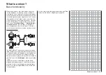
If you are unsure about the meaning of differential
travel, please read the appropriate explanation at the
start of this section on page 161.
The setting range of -100 % to +150 % permits correct
differentiation direction adjustment regardless of the
direction of rotation of aileron and fl ap servos.
A simultaneous tap on the
cd
or
ef
keys of the
right touch pad (
CLEAR
) will reset the given active
(inverse video) fi eld to its default value shown in
the fi gure.
Fl.pos
(fl ap position)
Fl.pos
Diff.
Ail-tr
Al
Normal
AILE
+100%
FL2
FLAP
0%
0%
0%
+100%
0%
+100%
0%
+100%
0%
0%
+100%
0%
0%
0%
FL
+100%
+100%
0%
0%
0%
0%
Here, you set the fl ight phase-specifi c wing fl ap
positions for all of the fl aps present on the model
in question. In this way, you can specify the fl ap
positions that apply to each fl ight phase.
The adjustment range of -100 % to +100 % makes
it possible to set the correct direction of travel
regardless of the direction of rotation of the aileron
and fl ap servos.
A simultaneous tap on the
cd
or
ef
keys of the
right touch pad (
CLEAR
) will reset the given active
(inverse video) fi eld to its default value shown in the
fi gures.
V
FL
V
(effect of fl aps)
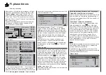
This line specifi es the percentage of effect produced
on aileron and fl aps by the settings (if applicable, also
fl ight-phase dependent settings) made for Input 6 in
the »
Control adjust
« menu, page 108.
Fl.pos
Diff.
Ail-tr
Al
Normal
AILE
+100%
FL2
FLAP
0%
0%
0%
+100%
0%
+100%
0%
+100%
0%
0%
+100%
0%
0%
0%
FL
+100%
+100%
0%
0%
0%
0%
For each fl ap pair, you can defi ne either a
symmetrical or an asymmetric effect. Position the
transmitter control accordingly – either centrally or to
the relevant side.
If each travel adjustment is left at +100 % on the
»
Control adjust
« menu, page 108, then values
between 5 % and 20 % should generally be suffi cient
here.
A simultaneous tap on the
cd
or
ef
keys of the
right touch pad (
CLEAR
) will reset the given active
(inverse video) fi eld to its default value shown in the
fi gures.
Note:
By default, NO transmitter control is assigned to input
6 on the »
Control adjust
« menu. However, you can
Summary of Contents for 32032
Page 1: ...33020 mc 20HoTT 2 en Programming Manual o Pro Pro mc 20 mc 20...
Page 15: ...15 For your notes...
Page 21: ......
Page 27: ...27 For your notes...
Page 41: ...41 For your notes...
Page 53: ...53 For your notes...
Page 59: ...59 For your notes...
Page 63: ...63 For your notes...
Page 93: ...93 For your notes...
Page 97: ...97 For your notes...
Page 141: ...141 How is a ight phase programmed...
Page 145: ...145 For your notes...
Page 155: ...155 For your notes...
Page 175: ...175 For your notes...
Page 203: ...203 For your notes...
Page 219: ...219 For your notes...
Page 253: ...253 For your notes...
Page 283: ...283 For your notes...
Page 321: ...321 For your notes...
Page 322: ...322 For your notes...
Page 323: ...323 For your notes...


