Page
8/14
Introduction
This charger is intended for direct connection to a easily accessible 110~240 (50/60HZ) mains supply
socket near to the charger, and is designed to charge Nickel-Cadmium, Nickel-Metal-Hydride and
lead-acid batteries. It is comprehensively protected against overload and short-circuit, and requires no
maintenance. Separate charge indicator LEDs are fitted for each charge output.
About charging and LED indicator
1
This charger has 7 output ports (OUTPUT1~OUTPUT7).
If you use a transmitter with protection diode against wrong polarity use only OUTPUT 2 or
OUTPUT 4 - 7.
Charging batteries
When a battery is charged, a particular quantity of electrical energy is fed into the
battery, which can be calculated by multiplying charge current by charge time. The
maximum permissible charge current varies according to the type of cells in the
pack; the figure can be found in the data sheet supplied by the battery manufacturer.
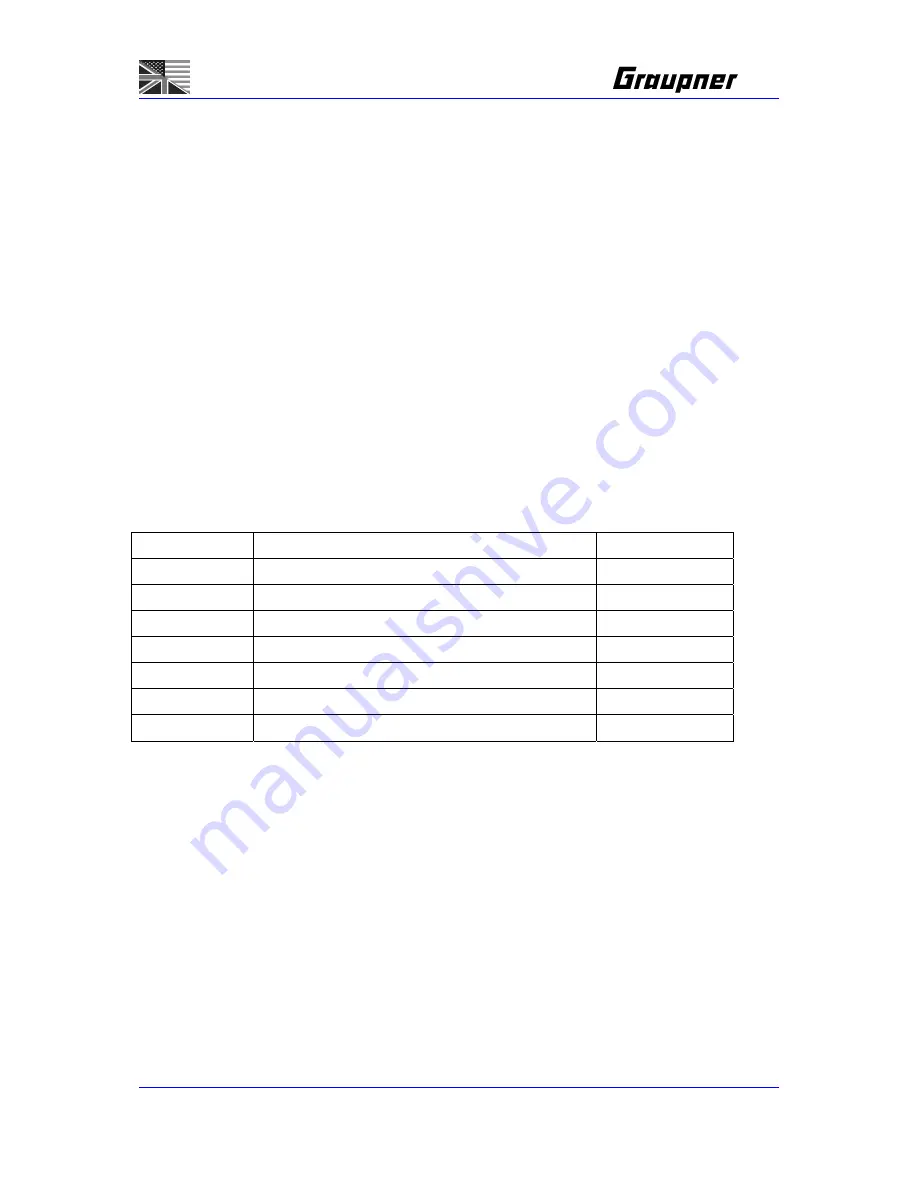
To prolong the service life of the battery, please select the correct charge current (charge port) as
follows:
Charge
Battery
Charge
Current
OUTPUT1
4~10 cells NiMh/NiCd Pack
1A~2A
OUTPUT2
4~10 cells NiMh/NiCd Pack
0~500mA
OUTPUT3
1~4 cells NiMh/NiCd Pack
0~500mA
OUTPUT4
1~10 cells NiMh/NiCd Pack
0~250mA
OUTPUT5
1~10 cells NiMh/NiCd Pack
0~250mA
OUTPUT6
1~10 cells NiMh/NiCd Pack
0~120mA
OUTPUT7
1~10 cells NiMh/NiCd Pack
0~120mA
* OUTPUT4,OUTPUT5,OUTPUT6, OUTPUT7 can also charge lead-acid batteries.
Note:
The following types of battery must not be connected to charger:
-Faulty or damaged cells or batteries.
-Non-rechargeable batteries (dry cells).
Caution:
explosion hazard!
-Batteries which are not expressly stated by the manufacturer to be suitable for the currents which the
unit produces during the charging process.
-Packs which are already fully charged or hot , or only partially discharged.
-Batteries installed in a device, or which are electrically connected to other components.
OUTPUT1~OUTPUT3:
These three outputs is using a -
△
V detection to control the charging process.
The figure below shows the voltage conditions of the battery connected to the OUTPUT1~OUTPUT3
outputs during charging. When the MCU detect a voltage drop (-
△
V) on top of the peak voltage, the
battery will be fed a trickle current to achieve a maximum charge effect.
Summary of Contents for 6455
Page 24: ...Page 11 14 ...


