•
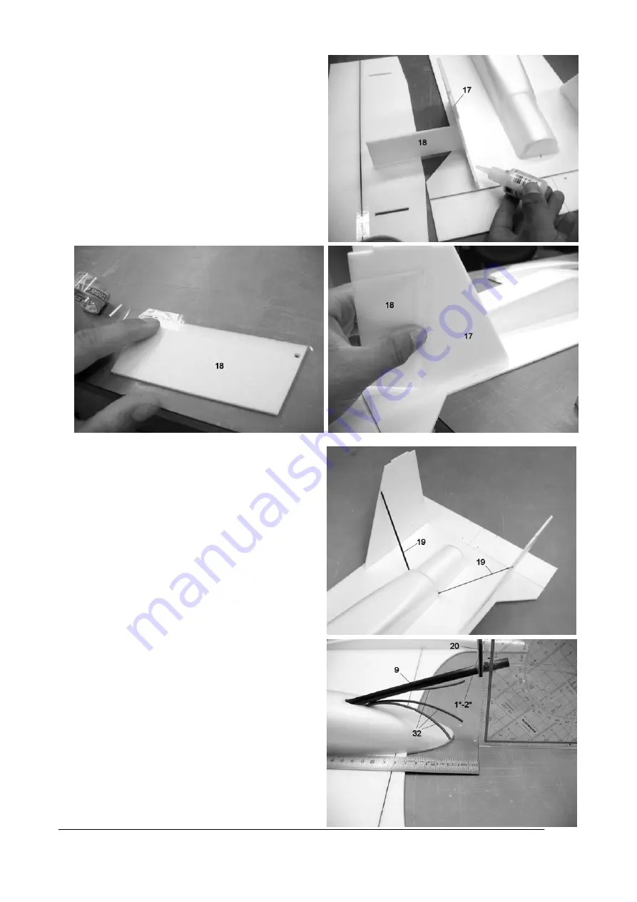
Glue the vertical fins (part 17) to the hull wing. Use
the rudders (part 18) to help alignment, and fit the
tailplane on the projecting lugs (but don’t glue them
at this stage). Check that the fins are correctly
aligned, then glue the tail panels in place using
foam cyano.
•
Sand both rudders to a 45° chamfer to form a
mirror-image pair, with both chamfers located on
the inside of the fins. Reduce the length of the
rudders until there is at least 0.5 mm clearance top
and bottom. Fix the control surfaces in place using
full-length strips of adhesive tape. Check once
again that the control surfaces are free to move to
both sides of centre.
•
Fit the rudder reinforcements (part 19) in the upper
hull shell, and rest the reinforcements against the
rudders. Glue the reinforcements to the hull and
the control surfaces using foam cyano, taking care
to produce strong joints. Now remove the elevator
again. The elevator should be attached
permanently at a later stage, as it gets in the way
of painting the model if you install it now.
•
Fit the motor bulkhead (part 20) on the motor
mount tube and set it straight relative to the
vertical axis. The motor mount should be angled
towards the rear by about 1° to 2° relative to the
longitudinal axis. Check that the distance from the
front hull reinforcement to the motor bulkhead is
about 80 mm. With the plate aligned as described,
glue it in place using cyano, taking care to produce
a sound joint. The tube can now be cut to length,
and sanded back flush with the plate. NOTE: the
motor bulkhead is designed in such a way that it
can be glued in place in both directions.
GRAUPNER GmbH & Co. KG D-73230 KIRCHHEIM/TECK GERMANY
Keine Haftung für Druckfehler. Technische Änderungen vorbehalten! No liability for printing errors. We reserve the right to introduce modifications. Sous réserve de modifications! Nous ne sommes pas responsables
d’éventuelles erreurs d’impression!
#56543
08/2005
23


