background image

INNOVATION & TECHNOLOGY 

REV 1 

16 

The GR-18 can log important flight data to any HoTT radio equipped 
with an SD memory card. Setting one is the default for telemetry log 
settings.  

Selectable Values: 

0 = No logging 
1 = Roll and Nick logging 

CALIBR. POSITION


To assure a stable and level flight in attitude mode the sensors need 
to be calibrated. To calibrate the sensors place your multicopter on a 
level surface and set the value to Yes. After a moment, it jumps back 
to  No  and  calibration  is  completed.  Do  not  forget  to  store  this  new 
setting which is done by unselecting the field! 

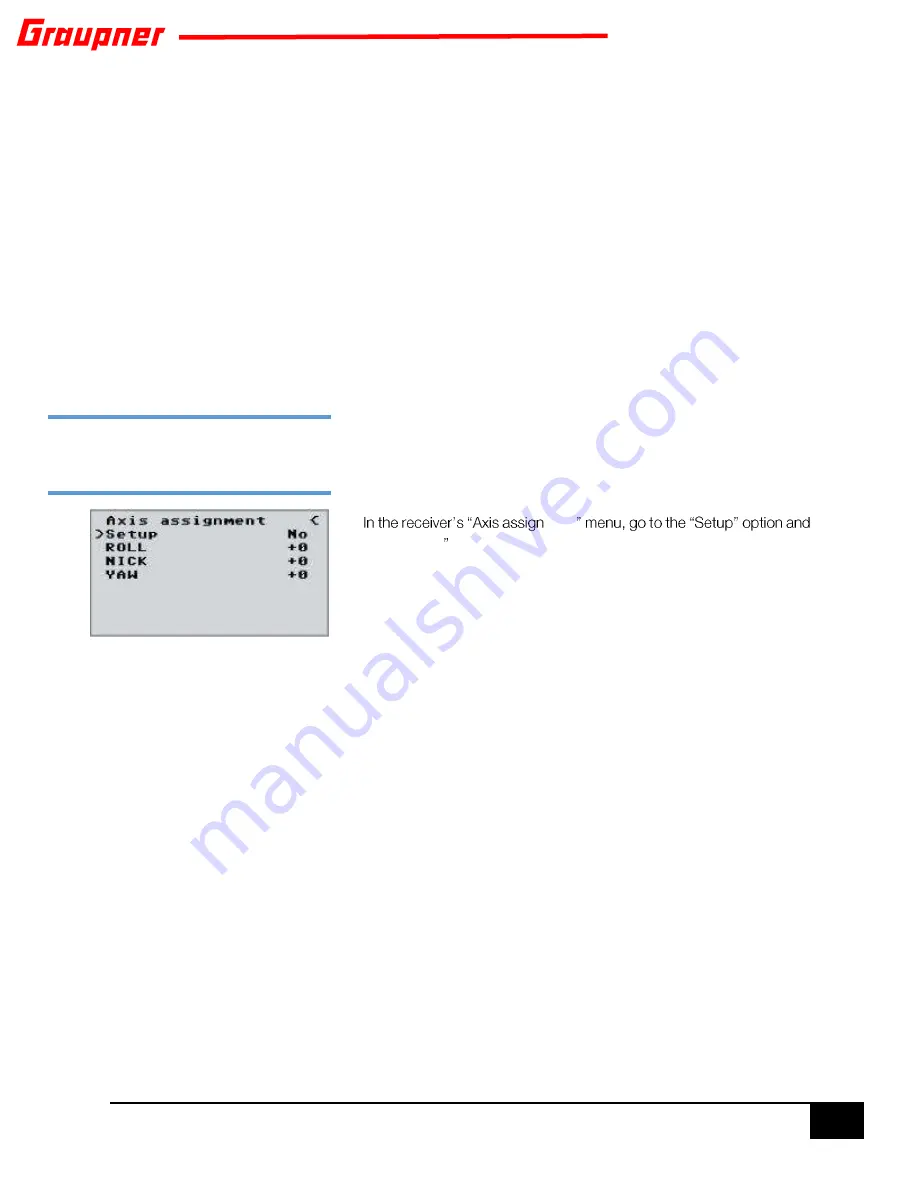
Axis assignment 

SETUP


Depending  on  the  way  you  installed  your  GR-18  it  must  now  learn 
proper  flight  orientation  in  order  to  respond  properly  to  the  radio 
steering commands. 

ment

set it to YES . Now assign the axes as follow: 

On the transmitter, briefly move the roll (aileron) stick briefly fully to the 
right and verify that the ROLL axis is highlighted. Roll the Multicopter 
more than 45 degrees to the right until the ROLL axis field is no longer 
highlighted which indicates the identification of this axis is complete. 

Now do the same for pitch (NICK) on the transmitter by pushing your 
pitch stick (elevator) briefly fully forward and verify that the NICK axis 
is highlighted. Tilt the Multicopter more than 45 degrees forward until 
the field is no  longer highlighted  which indicates the  identification  of 
this axis is complete. 

Finally complete the procedure for the rudder (YAW) on the transmitter 
by moving the rudder stick briefly and fully to the right and verify that 
the YAW axis is highlighted. Rotate the Multicopter so that the nose 
rotates more than 45 degrees to the right until the field is no longer 
highlighted which indicates the identification of this axis is complete. 

The gyros and flight orientations have now been assigned.  

To verify proper operation of your Multicopter you can test it as follows; 

Make sure that all propellers are removed from your Multicopter!   


Throttle up approximately 30% of power and verify that all motors 
run at the same speed.  

STEP THREE:

 Teach your multicopter 

proper flight orientation


Summary of Contents for Hott Alpha 250Q

Page 1: ...User Manual Alpha 250Q Race Copter User Manual No 16520 HoTT and 16520 RTF...

Page 2: ...pha 250Q RFH Preparations 6 Propeller Installation 6 BEFORE FLIGHT Safety checklist 7 Your First Flight 7 Telemetry RTF 8 Fail Safe 8 MZ 12 Radio setup 8 GR 18 FLIGHT CONTROLLER 10 Intended Use 11 MUL...

Page 3: ...ver better performance less noise and longer flight times SERVICE CENTRES Graupner USA OPENHOBBY LLC 3245 University Ave Suite 1520 San Diego CA 92104 United States Service Hotline 1 855 572 4746 Mon...

Page 4: ...or all kinds of model operation If you already have one check out whether the operation of the model is covered If applicable extend it to special model liability insurance We recommend to provide the...

Page 5: ...cable Yes ALPHA 250Q SPECIFICATIONS Expertly built no assembly needed Integrated triple mode receiver and flight controller Selectable flight modes beginner to expert Receiver with out of the box bui...

Page 6: ...e balance plug from the battery into the charger 3S 11 1V balancing port Charging may take up to 10 hours depending on the state of the battery 2 Install the supplied AA batteries into the mz 12 radio...

Page 7: ...a two position on off switch to channel 5 for your flight conditions Attitude Rate mode 3 Before attaching the 3S battery to the Alpha 250Q make sure that the throttle stick is all the way down and t...

Page 8: ...such as trees and electrical light poles Before attaching the battery always make sure that the throttle hold is in the ON position and that your throttle stick is always pointing backwards towards yo...

Page 9: ...a range of telemetry information that can be called at any time during flight In order to hear telemetry voice announcements a headset or ear piece needs to be plugged into the back of the mz 12 DSC...

Page 10: ...STEP FOUR Go to the D R expo menu Setting a bit of expo will make control a smoother for the beginner You can change settings later STEP FIVE Go to the RF sett menu Set stick mode to 2 and the timer f...

Page 11: ...xa V Hexa I Tri L Tri R The GR 18 controller has two build in flight modes to enable different flight responses to your multi multicopter The GR 18 controller is also very easy to setup and requires m...

Page 12: ...nd capabilities This receiver is not a toy It is not suitable for children under the age of 14 The installation and operation of the controller must be performed by experienced modellers If you do not...

Page 13: ...ositive wire is red and the signal wire is orange or white The socket for channel 8 K6 in GR 18 can also be programmed to provide a digital sum signal see next section Battery Power The receiver does...

Page 14: ...e receiver is switched on the indicated height is therefore the altitude relative to the launch point ground Cycle time PERIOD If your system is used exclusively with digital servos you can set a cycl...

Page 15: ...he throttle from accidental stick movements For additional information as to how to setup a throttle HOLD consult your radio manual The GR18 controller provides two flight modes to control your multic...

Page 16: ...been successfully completed you should from ESC SET to NORMAL Note For safety reason the Type and Mode changes take effect after switching off and on the GR 18 receiver Which consequence this paramet...

Page 17: ...than 45 degrees to the right until the ROLL axis field is no longer highlighted which indicates the identification of this axis is complete Now do the same for pitch NICK on the transmitter by pushin...

Page 18: ...in order to prevent a up climb at full throttle ROLL NICK D Now adjust the D component in steps of 5 until the Multicopter engages exactly on nick and roll A too high value may cause high oscillations...

Page 19: ...snap to yaw Higher values result in a faster engagement At too high P values the Multicopter the value must be reduced Yaw I Factor Standard setting 15 The I factor ensures constant rotations Start w...

Page 20: ...der no 7168 6 The connectors are reverse polarity protected note the small chamfers on the sides Never use force the connectors should engage easily connectors are reverse polarity protected note the...

Page 21: ...0 Connect the receiver and switch it on The progress bar shows that the transfer is running normally The receiver LED lights up red and green during this process and flashes red and green alternately...

Reviews: