Contents
3
General Section 4 – 7
Codes of the PROFI-ULTRASOFT-MODULE 4
General Information 5
Selection of Model Type 6 – 7
Mode of Operation – Code Menu 7
Analogue Adjustment of Values 7
Fixed-wing model section 8 – 56
Control Connections, Receiver Outlets 8 – 9
Model Type Block Diagrams 10 – 16
Code Chart – Model Types 1 – 5 17
Description of Options – Model Types 1 – 5 18 – 35
Code Chart – F3B Models - Types 6 – 7 36
Description of Options – F3B Models 38 – 43
Fixed-wing Programming Examples
I. Basic Settings
1. Preparations 44
2. Executing a Reset 44 – 45
3. Selection of Model Memory 45
4. Input Name of Model 45
5. Allocation of Control Sticks 46
6. Determining the Type of Model 46 – 47
7. Determining the Idle Trim 47
8. Copying the Settings 48
9. Determining the Modulation Mode 48 – 49
10. Adjusting the Direction of Servo Travel 49
11. Adjusting Servo Throw 50 – 51
II. Supplementary Adjustments
1. Limiting Servo Throw 52
2. Coordination of Throttle Characteristics 52 – 53
3. Storage of Trim Data 35
III. Examples of Copying
Single Model Memory 54
All Models Memory 55
Internal Copying 56
Helicopter Section 57 – 118
Receiver Outlets 57
Control Connections 58
Code Chart – Helicopter – Type 8 59
Description of Options – Helicopter Type 8 60 – 87
Description of Options – Helicopter Type 9 87
Helicopter Programming Examples
I. Basic Settings
1. Preparations 88
2. Executing a Reset 88 – 89
3. Selection of Model Memory 89
4. Input Name of Model 89
5. Allocation of Control Sticks 90
6. Determining the Type of Model 90 – 91
7. Direction of Throttle / Pitch Control Stick 91
8. Allocation of Switches 92
9. Copying the Settings 92 – 93
10. Determining the Modulation Mode 93
11. Type of Swashplate 94
12. Direction of Torque Compensation 94 – 95
13. Switching Activation of Auto-rotation 95
14. Adjusting Servo & Rotor Mixer Direction 96 – 97
15. Pitch Adjustments 97 – 99
16. Adjusting Torque Compensation 99
17. Adjusting Carburettor Actuation 100 – 101
II. Upgrading for Advanced Pilots
1. Throttle Preset 102
a. By Slider Control 102 – 103
b. By Switch 103
c. By Switch and Slider Control 103
2. Complementing Auto-Rotation Settings 104
a. Maximum Pitch 104 – 105
b. Minimum Pitch 105
c. Tail Rotor Centre Position in Auto-Rot’n 106
3. Compensating for Tail Rotor Load 106 – 107
III. Further Upgrading for Expert Pilots
1. PROFITRIM Module 108
a. Test Flying with PROFITRIM 108
b. PROFITRIM for Competition Use 109
2. Changeover from Hover to Aerobatics 110
a. Normal Adjustments for Aerobatics 110
b. Alternative Adjustments for Hover 111 – 115
3. Changeover to Auto-Rotation 116
4. Flare Compensation 117 – 118
Appendix
Changes from the MULTISOFT-Module 118 – 119
Summary of Contents for mc-18
Page 1: ...1...
Page 10: ...Block Diagram NORMAL 10...
Page 11: ...Block Diagram NORMAL DIFF 11...
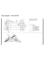
Page 12: ...Block Diagram DELTA DIFF 12...
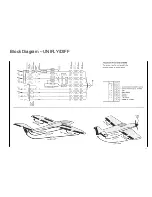
Page 13: ...Block Diagram UNIFLY DIFF 13...
Page 14: ...Block Diagram Quadro Flap 14...
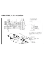
Page 15: ...Block Diagram F3B 3 wing servos 15...


